
Manual - Curtis Instruments
WIRING: STANDARD INSTALLATION, 1212 The wiring diagram presented in Figure 3a shows a typical installation for a DME application. This installation is shown with a single-ended 3-wire 5k potentiometer throttle and a reverse switch. Ω With wigwag throttles, a reverse switch is not used and Pin J1-12 is left unconnected.
Download Manual - Curtis Instruments

Information
Domain:
Source:
Link to this page:
Documents from same domain

AC Motor Controller with VCL - Curtis Instruments
cdn.curtisinstruments.comTogether with the Curtis model 3141 CAN LCD display and the user-friendly Curtis Integrated Toolkit, the Curtis model AC F2-A is the ultimate Class III truck control system. FEATURES Fit for Purpose Compact, rugged housing with very small ‘footprint’ for its power rating. Heavy duty M6 busbars for motor and battery connectors.

AC Motor Controller and DC Pump System Controller
cdn.curtisinstruments.comTogether with the Curtis model 3141 CAN LCD display and the user-friendly Curtis Integrated Toolkit, the Curtis model AC F2-C is the ultimate Class III truck control system. FEATURES High efficiency, field-oriented motor control algorithms. Fully integrated Half-bridge hydraulic pump controller that is configurable for various hydraulic

On-Road AC Motor Controller Model 1239E
cdn.curtisinstruments.comReverse polarity protection on battery connections. Short circuit protection on all output drivers. Thermal cutback, warning, and automatic shutdown provide protection to motor and controller. Rugged sealed housing and connectors meet IP65 environmental sealing standards for use in harsh environments. Meets or complies with relevant US
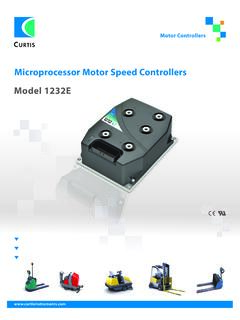
Microprocessor Motor Speed Controllers Model 1232E
cdn.curtisinstruments.comwarranty two year limited warranty from time of delivery. ksi switch 1/ana 1 switch 3 switch 4 switch 5 switch 6 switch 7 switch 8 coil return driver 1 driver 2 driver 3 driver 4 keyswitch encoder battery 24 i/o ground can h serial port switch 2/ana 2 throttle pot high throttle wiper pot 2 wiper pot low j1-24 j1-9 j1-10 j1-11 j1-12 j1-22 j1-33 ...
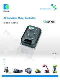
AC Induction Motor Controller Model 1234E - Curtis …
cdn.curtisinstruments.comMotor Braking Torque c Category 2 ≥16 yrs ≥90% Model Battery Voltage Nominal (V) 2 Minute RMS Current Rating (A) S2–60 Min RMS Current Rating 1234E-23XX 24 350 175 1234E-52XX 36–48 275 140 1234E-53XX 36–48 350 175 1234E-62XX 48–80 250 110 Contact Curtis to obtain the VCL Vehicle Control Language compiler and development tools.
SERIES - Curtis Instruments
cdn.curtisinstruments.com6 5 display position encoder b+ u v w b– main j1-31 j1-32 j1-7 j1-26 i/o gnd phase a phase b 1 2 4 3 ac motor switch 16 j1-19 digital driver 6 em rev. load hold valve lower lift mode motor temp. input t +12v (100ma) +5v (100ma) emergency stop wiring diagram 1232 ac induction motor controller pump cont digital driver 7 j1-20 j1-30 analog out ...
Models 1204M/05M/09M/21M - Curtis Instruments
cdn.curtisinstruments.comaluminum extruded housing. 3 Simple mounting and wiring with push-on connectors for control signals. 3 Plated solid copper buses used for all power connections. 3 Thermal protection and compensation circuit provides ... (#18 AWG) vinyl insulated stranded wire
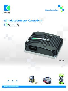
AC Induction Motor Controllers - Curtis Instruments
cdn.curtisinstruments.comforward reverse throttle pot pot 2 pv driver j1-2 can term h j1-21 j1-34 can term l short for 120 pot 2 ohm termination high j1-27 prop. valve 8 6 5 display speed encoder b+ u v w b– main j1-31 j1-32 j1-7 +5 v j1-26 i/o gnd phase a phase b 1 2 4 3 ac motor j1-19 digital output 7 j1-20 digital output 6 emr check (optional) em rev. mode motor ...

This document contains BOTH the - Curtis Instruments
cdn.curtisinstruments.comPaste, Drag & Drop). BATTERIES A compartment on the back holds two AA sized batteries. The batteries keep the real-time clock running and are used to power the 1313 HHP when working offline. Although the batteries can be used to power the 1313 while connected to a controller, operations such as data logging may quickly deplete the batteries.
Related documents

Z-45/22 DC Z-45/22 GP - Genie
manuals.gogenielift.comSerial Number Range Z-45/22 DC from SN 4587-124 to 4592-3600 Z-45/22 GP Part No. 139544 Rev A15 October 2013

Operating instructions ESV SMV frequency inverter - Lenze
download.lenze.comregarding the installation, operation, and commissioning of the inverter. These instructions are only valid for SMV frequency inverters with software revision 4.23 or higher for version 4.23 software, the drive nameplate illustrated below would show “42” in the “F” location.

express - Digitrax
www.digitrax.comthe Direction/Brake Lever to either FORWARD or REVERSE, depend-ing on which way you want the locomotive to move, and slowly turn the Throttle Knob clockwise until the locomotive starts to move. 8. To stop the locomotive, either turn the Throttle Knob back to STOP, or shift the Direction/Brake Lever to BRAKE. 3.0 Preparing Your Locomotives
INSTALLATION INSTRUCTIONS E-Z-GO Installation Notes
www.hpevs.comDec 21, 2010 · INSTALLATION INSTRUCTIONS . E-Z-GO Installation Notes. CURTIS 1234, 1236 OR 1238. ... Forward/Reverse switch and press the accelerator pedal. The drive wheels could be in either direction when first turned on. ... Select Forward Direction, Release Parking Brake, Press and hold the ...
OPERATING MANUAL - Sunflower Rental
www.sunflowerrental.com2. tail, brake, and reverse lights 3. seat 4. counterweight 5. steering axle 6. seat belt and hip restraint 7. drive axle 8. carriage 9. forks 10. load backrest extension 11. parking brake 12. steering wheel 13. mast 14. operating manual (behind seat) model description 10

T300 Operator Manual - Tennant Co
www.tennantco.com16. Forward/Reverse lever (drive model) 17. Control panel display 18. Emergency stop button (option) 19. Hour meter 20. Key switch 21. ec-H2O on/off switch (option) 22. Off-board battery charger receptacle 23. Recovery tank drain hose 24. Solution tank level/drain hose 25. Parking brake (option) 26. Dual down pressure lever (Manual down ...

T300e Operator Manual - Tennant Co
www.tennantco.comParking brake (option) Forward / Reverse (drive model) On Off No Solution flow CONTROL PANEL COMPONENTS 123 4 1. Service indicator- Lights up when a machine or charger fault is detected. 2. Parking brake indicator (option)- Lights up when parking brake lever is engaged. To turn off indicator, disengage parking brake lever near left rear wheel. 3.