MIL-STD-750D, Test Methods for Semiconductor Devices
Test methods numbered 5000 to 5999 inclusive are for high reliability space applications. 1.2.2 Revisions. Revisions are numbered consecutively using a period to separate the test method number and the revision number. For example, 4001.1 is the first revision of test method 4001. 1.3 Method of reference.
Download MIL-STD-750D, Test Methods for Semiconductor Devices

Information
Domain:
Source:
Link to this page:
Documents from same domain

Appendix H - TS9090-310G Approved 2015-2-16
www.navsea.navy.milts9090-310g sl720-aa-man-030 h-i navy modernization program management and operations manual (nmp-mom) appendix h alterations to ships accomplished by

THE - Naval Sea Systems Command
www.navsea.navy.milOn December 23, 2016, President Obama signed into law the National Defense Authorization Act (NDAA) of fiscal year (FY) 2017. Section 1111 modifies 5 United
STANDARD PHRASEOLOGY SECTION G NOTE: USE …
www.navsea.navy.milThis section of standard phraseology is for general use in ... COMUSFLTFORCOMINST 4790.3 72 of 75 18 NOV 2016/FY-18 FOR BUTTERFLY VALVES INSTALLED IN …
MIL-STD-750D, Test Methods for Semiconductor …
www.navsea.navy.milMIL-STD-750D Test Methods for Semiconductor Devices. MIL-STD-750D 1. This Military Standard is approved for use by all Departments and …
JESD22-A112-A Page 1
www.navsea.navy.miljesd22-a112-a page 2 test method a112-a test method a112-a moisture-induced stress sensitivity for plastic surface mount devices (from jedec council ballot jcb-95-37,
APPLIED ENGINEERING PRINCIPLES MANUAL
www.navsea.navy.milAPPLIED ENGINEERING PRINCIPLES MANUAL ... Chapter 1 ELECTRICAL REVIEW ... 1.1 Fundamentals Of Electricity ...
NAVAL SEA SYSTEMS COMMAND JOINT FLEET …
www.navsea.navy.milcomfltforcominst 4790.3 vii-4e-3 06 jan 2014/fy-15. naval sea systems command . joint fleet maintenance manual (jfmm) volume vii . chapter 4 . contract specification development
NAVSEA STANDARD ITEM NUMERICAL INDEX FY …
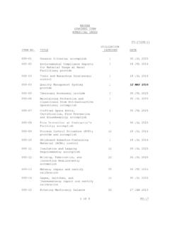
www.navsea.navy.mil1 of 8 FY-17 NAVSEA STANDARD ITEM NUMERICAL INDEX FY-17(CH-1) ITEM NO. TITLE UTILIZATION CATEGORY DATE 009-01 General Criteria; accomplish I 30 JUL 2015

Program Executive Office Integrated Warfare …
www.navsea.navy.milProgram Executive Office Integrated Warfare Systems (PEO IWS) Cybersecurity Industry Day October 30, 2015

OPNAV 5239/14 (Rev 9/2011) - Naval Sea Systems …
www.navsea.navy.milOPNAV 5239/14 (Rev 9/2011) REPLACES (Rev 7/2008), WHICH IS OBSOLETE Page 1 of 4FOR OFFICIAL USE ONLY WHEN FILLEDAUTHORITY: Executive Order 10450, Public Law 99-474, the Computer Fraud and Abuse Act; and System of Records Notice: NM0500-2 Program SYSTEM AUTHORIZATION ACCESS REQUEST NAVY (SAAR …
Related documents
PESD1CAN CAN bus ESD protection diode
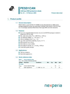
assets.nexperia.comCAN bus ESD protection diode Fig 7. ESD clamping test setup and waveforms 006aaa259 50 Ω RZ CZ D.U.T. (Device Under Test) vertical scale = 200 V/div horizontal scale = 50 ns/div unclamped +1 kV ESD voltage waveform (IEC 61000-4-2 network) clamped +1 kV ESD voltage waveform (IEC 61000-4-2 network) unclamped −1 kV ESD voltage waveform (IEC ...
1756 ControlLogix I/O Specifications
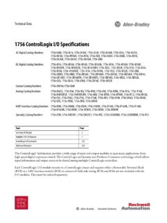
literature.rockwellautomation.com6 Rockwell Automation Publication 1756-TD002M-EN-E - December 2019 1756 ControlLogix I/O Specifications On-state current, min 5 mA @ 74V AC On-state current, max 16 mA @ 132V AC Inrush current, max 250 mA Input impedance, max 8.25 kΩ @ 132V AC, 60 Hz

FAILURE MECHANISM BASED STRESS TEST QUALIFICATION …
www.aecouncil.comMIL-STD-750 Test Methods for Semiconductor Devices 1.2.2 Industrial UL-STD-94 Test for Flammability of Plastic Materials of Parts in Devices and Appliances. JEDEC JESD-22 Reliability Test Methods for Packaged Devices J-STD-002 Solderability Tests for Component Leads, Terminations, Lugs, Terminals and Wires.

Charged Device Model (CDM) – Component Level
www.esd-resource.comdischarge (ESD) sensitivity of components to the defined charged device model (CDM). 1.2 Purpose The purpose of this document is to establish a test method that simulates CDM failures and provides reliable and repeatable results from tester to tester. This will allow accurate comparisons of component CDM ESD sensitivity levels.

PESD1LIN LIN-bus ESD protection diode - Nexperia
assets.nexperia.comLIN-bus ESD protection diode Fig 5. ESD clamping test setup and waveforms 006aaa166 50 Ω RZ CZ vertical scale = 200 V/div horizontal scale = 50 ns/div unclamped +1 kV ESD voltage waveform (IEC 61000-4-2 network) clamped +1 kV ESD voltage waveform (IEC 61000-4-2 network) unclamped −1 kV ESD voltage waveform (IEC 61000-4-2 network)

PESD2CAN CAN bus ESD protection diode - Nexperia
assets.nexperia.comCAN bus ESD protection diode Fig 9. ESD clamping test setup and waveforms 006aaa941 50 Ω RZ CZ D.U.T. (Device Under Test) unclamped +8 kV ESD pulse waveform (IEC 61000-4-2 network) clamped +8 kV ESD pulse waveform (IEC 61000-4-2 network), Pin 1 to 3 unclamped −8 kV ESD pulse waveform (IEC 61000-4-2 network) clamped −8 kV ESD voltage waveform
Charged Device Model (CDM) Qualification Issues - JEDEC
www.jedec.org< 250V •Basic ESD control methods with grounding of metallic machine parts and control of insulators + •Process specific measures to reduce the charging of the device OR to avoid a hard discharge (high resistive material in contact with the device leads). V CDM < 125V •Basic ESD control methods with grounding of metallic machine

MAY 1999 JOINT INDUSTRY STANDARD - Naval Sea Systems …
www.navsea.navy.milCracking Task Group, B-10a, and the JEDEC JC-14.1 Committee on Reliability Test Methods for Packaged Devices.) 1 Foreword The advent of surface mount devices (SMDs) introduced a new class of quality and reliability concerns regarding package cracks and delamination. This document describes the standardized levels of floor life

AN3353 Application note - STMicroelectronics
www.st.comtest methods, and the specified levels are most of the time the maximum standard levels. ... ESD test bench for STMicroelectronics protection devices Our device is soldered on a dedicated PCB as shown in Figure 3. A 2 mm female banana plug is connected to the ground plane of the PCB. This plug, through the bleeder resistors (2