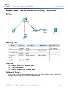
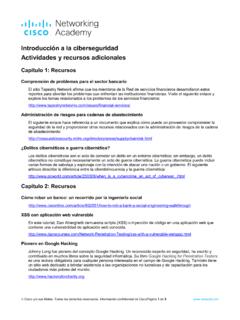
Packet Tracer Explore Network Functionality Using PDUs
Observe the information in the OSI Model tab. Notice that this is an outbound Layer 3 PDU and the source and destination IPv4 address is shown. Packet Tracer – …
Download Packet Tracer Explore Network Functionality Using PDUs

Information
Domain:
Source:
Link to this page:
Documents from same domain

Packet Tracer - Logical and Physical Mode Exploration
contenthub.netacad.comencounter in Cisco Networking Academy courses will use Logical mode. You can switch between these You can switch between these modes at any time to compare the differences by clicking the Logical (Shift+L) and Physical (Shift+P)

Packet Tracer Configure End Devices
contenthub.netacad.comPacket Tracer – Configure End Devices Objectives Configure various end devices in Packet tracer. Background / Scenario In this activity you will construct a simple Packet Tracer network and complete basic configuration of end devices. Step 1: Launch Packet Tracer. a. Launch Packet Tracer on your PC or laptop computer

Packet Tracer Modify Your Thing
contenthub.netacad.comIn the Server-Devices Window click on the Security Camera to expand the device information. Notice the Security Camera is On but not activated. Step 2: Activate the Security Camera. Move the Tablet configuration window out of the way but still visible so that the Packet Tracer workspace is visible.
Introducción a la ciberseguridad Actividades y recursos ...
contenthub.netacad.comCisco y/o sus filiales. Todos los derechos reservados. Información confidencial de CiscoPágina 1 de 5 www.netacad.com Introducción a la ciberseguridad . Actividades y recursos adicionales
Packet Tracer Modify and Monitor Environmental Controls in ...
contenthub.netacad.comPacket Tracer – Modify and Monitor Environmental Controls in Packet Tracer The Smart Home Network Objectives Part 1: Explore Environmental Controls Part 2: Edit Environment Elements Background / Scenario In this activity you will use the Physical view in Packet Tracer to view and edit the evironmental controls.

Packet Tracer Create a Simple Network Using Packet Tracer
contenthub.netacad.comPart 1: Build a Simple Network in the Logical Topology Workspace Step 1: Launch Packet Tracer. a. Launch Packet Tracer on your PC or laptop computer Double click on the Packet Tracer icon on your desktop or navigate to the directory that contains the Packet Tracer executable file and launch Packet Tracer.

Lab Create a Process Flowchart
contenthub.netacad.comLab – Create a Process Flowchart Objectives Part 1: Recognize Symbols Used in a Flowchart and List Logical Process to Solve a Problem Part 2: Draw the Flowchart to Illustrate the Problem Solving Process Background Flowcharts are diagrams used to represent processes or workflows. Using different shapes, boxes, and

Video Introduction to Packet Tracer
contenthub.netacad.comserver labs, we can see security with AAA, DNS, file servers, secure web browsing, email servers, and even go into IoT registration servers for our IoT devices. For now, we're going to head over to the PC directory, and then the VPN folder. In the VPN folder, there's a VPN Easy file that we can open up.

Lab - Mapping the Internet
contenthub.netacad.comLab - Mapping the Internet © 2018 Cisco and/or its affiliates. All rights reserved. This document is Cisco Public. Page 6 of 12 path, and the return time is measured ...

Packet Tracer Adding IoT Devices to a Smart Home
contenthub.netacad.comof the IoT device window, click the Advanced button. Notice more tabs become visible at the top of the window. Click the I/O Config tab. Change the Network Adapter drop down list to PT-IOT-NM-1W, which is a wireless adapter. f. Configure the Wind Detector for the wireless network.
Related documents
Chapter 3 OSI Model - EazyNotes
www.eazynotes.comPrinciples on which OSI model was designed: A layer should be created where different level of abstraction is needed. Each layer should perform a well defined function. The function of each layer should be chosen according to the internationally standardized protocols. The number of layers should be large enough that distinct functions should not be put in the same layer and small

CHAPTER FOUR OSI Model and Network Protocols
access.itxlearning.comEven though the OSI model is conceptual, an appreciation of its purpose and function can help you better understand how protocol suites and network architectures work in practical applications. The OSI Seven-Layer Model As shown in Figure 4.1, the OSI reference model is built, bottom to top, in the

OSI Reference Model - Router Alley
www.routeralley.comOSI Reference Model The Open Systems Interconnection (OSI) model was developed by the International Organization for Standardization (ISO), and formalized in 1984. It provided the first framework governing how information should be sent across a network. The OSI model consists of seven layers, each corresponding to a specific network function:
Internet Protocols
fab.cba.mit.eduOSI Reference Model Internet Protocol Suite Session NFS XDR RPC FTP, Telnet, SMTP, SNMP Not Specified IP ICMP TCP, UDP ith2801 Routing Protocols ARP, RARP. Internet Protocols 30-3 IP Packet Format Figure 30-2 Fourteen fields comprise an IP packet.
Data Communication and Computer Network
www.tutorialspoint.comhuge level, internet works on Client-Server model. Internet uses very high speed backbone of fiber optics. To inter-connect various continents, fibers are laid under sea known to us as submarine communication cable. Internet is widely deployed on World Wide Web services using HTML linked pages
TCP/IP Tutorial and Technical Overview
www.redbooks.ibm.comTCP/IP Tutorial and Technical Overview December 2006 International Technical Support Organization GG24-3376-07

INTRODUCTION TO PROFIBUS DP - Unict
www.diit.unict.itthe OSI (Open System Interconnection) reference model per international standard ISO 7498. In this model, every layer handles precisely defined tasks. Layer 1 of this model is the physical layer and defines the physical transmission characteristics. Layer 2 is the data link layer and defines the bus access protocol.

OSI Model Layers in Computer Networks PDF
ugcportal.comOSI Model Layers in Computer Networks PDF By Ramandeep Singh Page 1 OSI OSI stands for Open System Interconnection Model(OSI Model). It use to transfer data over a network which moves through different layer. It has 7 layer which divided into two level : upper or host & lower or media level data moves through different stages like (in ascending order) …

El modelo OSI - UNICEN
users.exa.unicen.edu.arreferencia OSI, especialmente cuando desean enseñar a los usuarios cómo utilizar sus productos. Los fabricantes consideran que es la mejor herramienta disponible para enseñar cómo enviar y recibir datos a través de una red. El modelo de referencia OSI permite que los usuarios vean las funciones de red que se producen en cada capa.