
Physical Explanation - Vishay Intertechnology
Switching on Characteristic Forward recovery time, tfr The time required for the voltage to reach a specified value (normally 110 % of the steady state forward voltage drop), after instantaneous switching from zero or a specified reverse voltage to a specified forward biased condition (forward current).
Download Physical Explanation - Vishay Intertechnology

Information
Domain:
Source:
Link to this page:
Documents from same domain

How to Select the Right MOSFET for Power Factor …
www.vishay.comVISHAY SILICONIX Power MOSFETs Application Note - AN844 How to Select the Right MOSFET for Power Factor Correction Applications APPLICATION NOTE Revision: 03-Jun-13 1 Document Number: 65677

Automotive P-Channel 60 V (D-S) 175 °C MOSFET
www.vishay.comSQ7415AEN www.vishay.com Vishay Siliconix S13-1891, Rev. C, 26-Aug-13 1 Document Number: 67042 For technical questions, contact: automostechsupport@vishay.com THIS DOCUMENT IS SUBJECT TO CHANGE WITHOUT NOTICE.

Transient Voltage Suppressors (TVS) for …
www.vishay.comTransient Voltage Suppressors (TVS) for Automotive Electronic Protection www.vishay.com For technical questions within your region, please contact one of the following: Document Number: 88490

Power Metal Strip Resistors, Low Value (down to …
www.vishay.comWSR High Power www.vishay.com Vishay Dale Revision: 11-Jul-2018 1 Document Number: 31059 For technical questions, contact: ww2bresistors@vishay.com THIS DOCUMENT IS SUBJECT TO CHANGE WITHOUT NOTICE.

Resistive Products Power Dissipation in High …
www.vishay.comDocument Number: 53048 www.vishay.com Revision: 29-Oct-09 1 VISHAY SFERNICE Resistive Products Application Note Power Dissipation in High Precision Vishay Sfernice Chip Resistors and Arrays

Vishay Semiconductors
www.vishay.comVCUT0505B-HD1 www.vishay.com Vishay Semiconductors Rev. 2.2, 16-May-17 1 Document Number: 81852 For technical questions, contact: ESDprotection@vishay.com THIS DOCUMENT IS SUBJECT TO CHANGE WITHOUT NOTICE.

RF PIN Diodes - Single in DO-35 (DO-204AH) - Vishay
www.vishay.comLegal Disclaimer Notice www.vishay.com Vishay Revision: 08-Feb-17 1 Document Number: 91000 Disclaimer ALL PRODUCT, PRODUCT SPECIFICATIONS AND DATA ARE SUBJECT TO CHANGE WITHOUT NOTICE TO IMPROVE

Small Signal Switching Diodes, High Voltage
www.vishay.comBAV17, BAV18, BAV19, BAV20, BAV21 www.vishay.com Vishay Semiconductors Rev. 1.9, 12-Jul-17 3 Document Number: 85543 For technical questions within your region ...

High Precision Wraparound - Wide Ohmic Value …
www.vishay.comP www.vishay.com Vishay Sfernice Revision: 23-Feb-18 1 Document Number: 53017 For technical questions, contact: sferthinfilm@vishay.com THIS DOCUMENT IS SUBJECT TO CHANGE WITHOUT NOTICE.

Aluminum Electrolytic Capacitors Radial Standard …
www.vishay.com038 RSU www.vishay.com Vishay BCcomponents Revision: 28-Feb-17 1 Document Number: 28309 For technical questions, contact: aluminumcaps1@vishay.com THIS DOCUMENT IS SUBJECT TO CHANGE WITHOUT NOTICE.
Related documents

Power Transformer Factory Test using IEEE Standards
r5.ieee.orgZero phase sequence voltage X Future/System reference Temperature rise X X Thermal and performance List of tests 8 Dielectric tests Routine Design Others Remark Lightning impulse X X Dielectric test Switching impulse X Dielectric test Applied voltage test X Dielectric test Induced voltage with or without
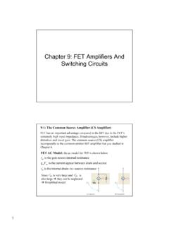
Chapter 9: FET Amplifiers And Switching Circuits
staff-old.najah.eduSwitching Circuits 9-1: The Common Source Amplifier (CS Amplifier) ... A zero-biased common-source amplifier for ... Determine the voltage gain and the input resistance of the amplifier in Figure 9–20. VDD is negative because it is a p-channel device. From data
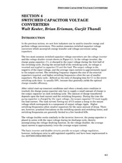
SECTION 4 SWITCHED CAPACITOR VOLTAGE CONVERTERS …
www.analog.comthe switching cycle. During the second half of the switching cycle, its voltage is inverted and applied to capacitor C2 and the load. The output voltage is the negative of the input voltage, and the average input current is approximately equal to the output current. The switching frequency impacts the size of the external
Switching regulator fundamentals (Rev. C) - Texas …
www.ti.com1. A voltage across an inductor results only from a current that changes with time. A steady (DC) current flowing in an inductor causes no voltage across it (except for the tiny voltage drop across the copper used in the windings). 2. A current flowing in an inductor can not change value instantly (in zero time), as this would require
Zero Voltage Switching - Texas Instruments
www.ti.comZero Voltage Switching Resonant Power Conversion Bill Andreycak ing zero current, hence zero power switching. And while true, two obvious concerns can in1pede the quest for high efficiency operation with high voltage inputs. By nature of the resonant tank and zero current switching limitation, the peak switch
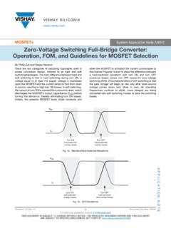
MOSFETs Zero-Voltage Switching Full-Bridge Converter ...
www.vishay.comswitching-related EMI, and eliminates the need for primary-side snubbers. Fig. 2 - Typical ZVSFB Circuit WHY ZERO-VOLTAGE SWITCHING When a MOSFET turns on, there are losses due to voltage and current overlap (Figure 3) and the discharge of stored energy in its Coss capacitor. In ZVS the Coss is tricked into