
Radio Technology Somfy® Pocket Programming Guide
1 How Does It Work? Simply press a button on a remote control or wall switch and window coverings move with ease. There is no need to point or …
Download Radio Technology Somfy® Pocket Programming Guide

Information
Domain:
Source:
Link to this page:
Documents from same domain

INSTALLATION AND USER GUIDE ENGLISH
service.somfy.comThis menu lets you programme a set of actions on your devices depending on your sensors. Example: I WANT my shutters to close. IF the sun shines brightly. 1. Click “new”. 3. Choose which sensor and condition will start the programme > IF. 2. Drag your devices to the box and define the actions to be performed > I WANT. 4. Save your programme and

PROGRAMMIERUNG Bedienung EINSTELLUNG
service.somfy.comE.3 Sender in RTS Technologie: Centralis RTS, Telis 1 RTS und Telis 4 RTS Aktion Resultat Signal Länger als 5 Sekunden den Programmier- Der ganze Speicher des Empfängers wird gelöscht, 8 kurze Piepstöne knopf des neuen Senders drücken. und die Adresse des neuen Senders gespeichert. Der Empfänger kehrt in den Normal-Modus zurück.
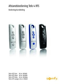
Bedieningshandleiding - service.somfy.com
service.somfy.comveiligheid Lees deze handleiding zorgvuldig door alvorens dit product te installeren en in gebruik te nemen. Elk gebruik dat buiten het door Somfy omschreven toepassingsgebied valt is verboden. Dit, als ook het niet naleven van de hierna gegeven instructies, doet de garantie vervallen en ontheft Somfy van elke aansprakelijkheid.

SOMFY INSTRUCTIONS TELIS RTS REMOTE CONTROLS …
service.somfy.comIn addition to standard OPEN and CLOSE features, the Telis remote enables the user to pre-establish a favorite stop location. a.k.a. “MY” favorite position. An example could be to command the RTS motorized window covering to a 50% or 75% open or closed position when the “MY” button is briefly pressed. OR Telis 5 RTS Transmitter only: 1a.
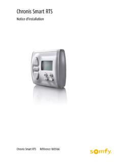
Notice d'installation
service.somfy.comTouche Mode de programmation Affichage de la date Touche de réglage et mode horloge Touche de programmation 1) Ouvrez la mémoire du moteur RTS ou du récepteur RTS. (Voir la notice du moteur ou du récepteur) 2) Appuyez sur le bouton PROG jusque PROG apparaît sur l'écran. avec une fréquence identique à celle de la Chronis Smart RTS,

EQUIPEMENTS IO-HOMECONTROL COMPATIBLES AVEC …
service.somfy.comRécepteur éclairage intérieur RTS 1 810 165 Récepteur éclairage extérieur RTS 1 810 628 Récepteur éclairage Slim RTS 1 822 215 Rampe d’élairage 1 et 3 mètres 1 811 022 ... Conformément à la norme, nous vous conseillons d'installer un jeu de cellules. Conformément à la norme, nous vous conseillons d'installer un jeu de cellules.

Premium - INSTALLATIONS- UND GEBRAUCHSANLEITUNG
service.somfy.com"neu". Ziehen Sie die Produkte und/ oder Szenarien in die Zone. 2. Wählen Sie die Sensoren und die Bedingungen, die die Programmierung auslösen sollen. Sobald eine Bedingung erfüllt wird, wird die Statusanzeige LED grün. Wenn alle Statusanzeigen LED grün sind, wird die Programmierung gestartet. Um alle Smart-Programmierungen zu deaktivieren,
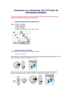
Programmation de la télécommande Telis 4 RTS
service.somfy.comProgrammation de la télécommande Telis 4 RTS depuis des télécommandes individuelles. La Telis 4 est composée de 5 canaux, les 4 premiers canaux sont représentés chacun par une lampe témoin, le cinquième canal par les 4 lampes qui clignote en même temps. 1. Répartition des volets roulants sur les différents canaux.

Smoove Origin RTS - service.somfy.com
service.somfy.comdie Anforderungen der Richtlinie 2014/53/EU erfüllt. Der vollständige Text der Konformitätserklärung ist unter der ... Programmazione di Smoove Origin RTS per un prodotto che non prevede un punto di comando Consultare la guida del motore RTS o del ricevitore RTS.

Programmation d'un volet roulant - service.somfy.com
service.somfy.comProgrammation d’un moteur de volet roulant Oximo RTS, Altus RTS ou Orea RTS. 1. Pré-mémoriser une télécommande de réglage. Appuyer en même temps sur les boutons « montée » et « descente » jusqu’au mouvement de va et vient du volet roulant
Related documents

Splendide
www.splendide.com1. Door Switch Test 41 2. Power “in” from the Surge Protector Test 42 3. Pressure Switch Test 43 4. Heating Element Test 44 5. Main Motor Test (Includes Running the Main Motor with AC Voltage) 45 6. Fan Motor / Water Pump Test 46 7. Water Valve / Wash NTC Test 47 8. Control Panel Board Test 48 9. Dry NTC Sensor Test 49 6.

Hall Effect Experiment Manual
d2n0lz049icia2.cloudfront.net14 2-Axis Magnetic Field Sensor PS-2162 1 ... • Do not defeat power cord safety ground feature. • Plug in to a grounded (earthed) outlet. • Do not use product in any manner not specified by the manufacturer. ... • Power switch: Turns the power to the instrument ON or OFF.

Troubleshooting Guide
downloads.hearthnhome.com2—Sensor rod acknowledges pilot flame is present before releasing gas to the main burner for ignition. When a pilot flame engulfs the sensor rod it conducts electrical current from the sen-sor through the flame to ground in one direction, which acts …

Instruction Manual - LMIPumpCatalog.com
lmipumpcatalog.comlevel float switch plus manual control adjustments of control code 1 External control capability through 4-20 mA input and low level float switch plus manual control adjustments of control code 1 See Most Recent Price List for Flow and Pressure Ratings 1 – 110-120V US Plug 2 – 220-240V US Plug 3 – 220-240V DIN Plug 4 – 220-240V Israel Plug
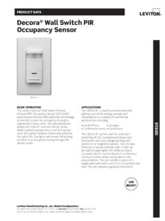
Decora Wall Switch PIR Occupancy Sensor - Leviton
www.leviton.comODS10-ID Decora Wall Switch Occupancy Sensor G-8333D/K17-aa REV NOV 2017 INSTALLATION The ODS10-ID may replace a single-pole wall switch mounted in a standard wallbox. The unit must be properly grounded in order to operate. The unit’s integral blinders may be used to restrict the field-of-view to prevent unwanted detection of hallway traffic.
Isolation in Electric Vehicle Systems Quick Reference
www.skyworksinc.comloading. The return, or ground, for the low-voltage side is normally connected to the vehicle chassis, so galvanic isolation between the low-voltage side and high-voltage side is required for safety as well as for protection of the LV controller. Isolation between the HV input and the LV output of the converter is accomplished using a transformer.

12K OUTDOOR - solar-electric.com
www.solar-electric.comA. LCD Touch Screen F. Sensor Pin-Out Board B. Power Button G. Comms/Paralleling Ports C. PV DC Disconnect Switch H. AC Breakers (Grid 63A/Gen 50A/Load 63A) D. 250A Battery Breaker I. Neutral/Ground Bus Bar E. Battery Terminals (+/-) J. MPPT Charge Controllers

INSTALLER'S GUIDE
www.trane.comThe pressure switch is factory preset at .45" WC. After a failure situation is detected and corrected, reset the Zone Sensor service light. This is done by either setting the mode switch to "OFF" for 5 seconds, then back to the desired mode or by cycling the power "OFF" then "ON" at the unit disconnect switch.