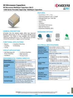
RF/Microwave Capacitors
• Capacitance Range 0.1pF to 1000pF • Extended WVDC up to 1500 VDC • Low ESR/ESL • High Q • Low Noise • Ultra-Stable Performance • High Self-Resonance • Established Reliability (QPL) PACKAGING OPTIONS Tape & Reel Cap Pac® (100 pcs) 032421 ELECTRICAL SPECIFICATIONS Temperature Coefficient (TCC) +90 ±20 PPM/°C (-55°C to +125°C)
Download RF/Microwave Capacitors

Information
Domain:
Source:
Link to this page:
Documents from same domain

RADIAL LEADS - datasheets.kyocera-avx.com
datasheets.kyocera-avx.comNPO typical characteristics, see the KYOCERA AVX Multilayer Ceramic Leaded Capacitors Catalog. STYLE* MAXIMUM CAPACITANCE VALUE C0G (NP0) X7R SR29 900 pF .015 μF SR20 1800 pF .033 μF SR28 SR59 900 pF .015 μF SR13 SR21 1800 pF .033 μF SR30 SR61 SR65 7200 pF .12 μF SR40 SR75.015 μF .27 μF SR22 1800 pF .033 μF SR27 1800 pF .033 …

TAJ – Standard & Low Profile TAJ Series
datasheets.kyocera-avx.com• Entertainment / Infotainment Systems • Height Restricted Design STANDARD CASE DIMENSIONS: millimeters (inches) LOW PROFILE CASE DIMENSIONS: millimeters (inches) XXXXX 227 A LOGO Capacitance Value in pF 227 = 220µF Rated Voltage Code A = 10V ID Code Polarity Band (Anode+) J 1 0 6 Capacitance Value in pF 106 = 10µF Rated Voltage Code …

GENERAL DESCRIPTION
datasheets.kyocera-avx.comGeneral Specifications GENERAL DESCRIPTION ... BOARD BEND TEST PROCEDURE According to AEC-Q200 BOARD BEND TEST RESULTS ... Soldering Reflow/Wave Reflow/Wave Reflow/Wave WVDC 25V 50V 25V 50V 25V 50V 271 Cap 270 G G 331 (pF) 330 G G J J 471 470 G G J J 681 680 G G J J 102 1000 G G J J J J

Automotive MLCC - datasheets.kyocera-avx.com
datasheets.kyocera-avx.com56 Automotive MLCC-NP0 Capacitance Range SIZE 0402 0603 0805 1206 Soldering Reflow/Wave Reflow/Wave Reflow/Wave Reflow/Wave WVDC 25V 50V 25V 50V 100V 200V 25V 50V 100V 200V 250V 25V 50V 100V 200V 250V 500V

PART NUMBER (SEE PAGE 4 FOR COMPLETE PART NUMBER …
datasheets.kyocera-avx.comX7R formulations are called “temperature stable” ceramics and fall into EIA Class II materials. X7R is the most popular of these intermediate dielectric constant materials. Its temperature variation of capacitance is within ±15% from -55°C to +125°C. This capacitance change is …

Low ESR Resin Molded Solid Tantalum Chip, J-Lead TPS ...
datasheets.kyocera-avx.comLow ESR Resin Molded Solid Tantalum Chip, J-Lead Low ESR TPS Series – Standard & Low Profile FEATURES • Low ESR Series of Robust Mn0 2 Solid Electrolyte Capacitors • 100% Surge Current Tested • CV Range: 0.15-1500μF / 2.5-50V • 14 Case Sizes Available • Power Supply Applications APPLICATIONS • General Medium Power DC/DC Convertors
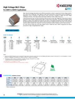
High Voltage MLC Chips
datasheets.kyocera-avx.com95 High Voltage MLC Chips For 600V to 5000V Applications Case Size 0805 1206 1210 1808 1812 Soldering Reflow/Wave Reflow/Wave Reflow Only Reflow Only Reflow Only (L) Length mm 2.10 ± 0.20 3.30 + 0.30 3.30 + 0.40 4.60 + 0.50 4.60 + 0.50

SECTION 2: SOLID CONDUCTIVE POLYMER ELECTROLYTIC …
datasheets.kyocera-avx.comtcj series section 2: solid conductive polymer ... tcjb107m002#0055e b 100 2.5 125 25 6 55 1500 1100 700 400 0 3 tcjb107m002#0070e b 100 2.5 125 25 6 70 1300 900 600 300 1 3 tcjb157m002#0070e b 150 2.5 105 37.5 6 70 1300 900 600 – 3 3 tcjb227m002#0035e b 220 2.5 105 55 8 35 1900 1300 900 – 3 3
Related documents
Understanding How Ferrites Can Prevent and Eliminate RF ...
audiosystemsgroup.comwaves that establish dimensional resonance to exist. Fig 12 A multi-turn choke To understand what’s happening, we’ll study Fig 12, our first order equivalent circuit of a multi-turn choke. LC and RC and CC are the inductance, resistance, (including the effect of the µ of the ferrite), and stray capacitance
DIY Magnetic Loop Antenna
www.cvarc.orgavoid self-resonance, the conductor length for a small transmitting loop antenna should be less than 1/4 wavelength (less than about 8.23 feet at the specified frequency of 29 MHz).” Well, I don’t want the wire in the loop to resonate by itself, its designed …

Syllabus of M. Sc. in Physics - University of Burdwan
buruniv.ac.inSelf force. (22 lectures) Books Recommended: 1. Marion- Classical Electrodynamics 2. Jackson- Classical Electrodynamics 3. Panofsky & Phillips- Classical Electrodynamics 4. Chen- Plasma Physics 5. Griffith-Electrodynamics Paper – 103 Unit – I : Solid State Physics I [23 Marks] 1. Crystalline and amorphous solids. The crystal lattice.

MULTILAYER CERAMIC CHIP CAPACITORS - TDK
product.tdk.com† Low self-heating value and high resistance to ripple on account of the ... † LC resonance circuit (C0G type) † Applications requiring high reliability ... For details such as the catalog numbers, please refer to the capacitance range table on page 12 and after.
MT-101: Decoupling Techniques - Analog Devices
www.analog.comThe self-resonant frequency of the capacitor is the frequency at which the reactance of the capacitor (1/ωC), is equal to the reactance of the ESL (ωESL). Solving this equality for the resonant frequency yields: 2 ESL C 1 fRESONANCE π ⋅ = . Eq. 1 All capacitors will display impedance curves which are similar in general shape to those shown.

Piezoelectric Accelerometers and Vibration Preamplifiers
www.bksv.comCh = Capacitance to the housing of a balanced accelerome-ter from the output pins Cable Electrical Quantities C" = Capacitance of cable R" = Series reslstance of cable Rb = Resistance between centre conductor and screen C" = Capacitance between screen and inner conductors In balanced accelerometer cable Cd = Capacitance of dielectric in
The Underestimated Magnetic Loop HF Antenna - Nonstop …
www.nonstopsystems.comA self-resonant antenna might be thought of as being "optimally efficient". Smaller loops require additional series or shunt capacitance to tune them to resonance so that the impedance presented to the feed becomes real, i.e. R +/−j0. In a self-resonant loop,it is clear that the standard small-loop theory breaks down.

AN11564 PN7120 Antenna Design and Matching Guide - NXP
www.nxp.comThe antenna parasitic capacitance Ca should be kept low to achieve a self-resonance frequency > 25 MHz as the relation linking those 2 parameters is: a. In order to get these antenna electrical equivalent parameters, 2 methods are proposed below depending on the available equipment: