
RobotWare - ABB
modules, e.g. for changing configuration. File and Serial Channel Handling includes instructions for communication via serial channels. This can be used to continuously store data (program output) on a disk or to use a bar code reader as input to the robot. 3
Download RobotWare - ABB

Information
Domain:
Source:
Link to this page:
Documents from same domain

Operating Instructions Head mounted Temperature ...
library.e.abb.comtemperature range for the transmitter and not to the measuring element used in the measuring inset. 1.6 Operator liability Before the use of corrosive and abrasive ...

ABB Ability™ Ellipse® for connected asset lifecycle …
library.e.abb.comABB Ability Ellipse Asset Performance Management (APM), formerly known as Asset Health Center, monitors asset health ... 1/9/2018 9:04:10 AM ...

Data Sheet Temperature sensors SensyTemp …
library.e.abb.comTemperature sensors SensyTemp TSP111, TSP121, ... - Measuring elements can be exchanged during ... Temperature sensors SensyTemp TSP111, TSP121, TSP131 …

Differential Pressure Flow Elements DP Primary …
library.e.abb.comDifferential Pressure Flow Elements DP Primary Elements ... temperature and pressure elements, ... and remote-seal DP transmitter elements can be

Technical guide No. 3 - EMC compliant installation …
library.e.abb.comPower cables ... Technical guide No. 3 | EMC compliant installation and configuration for a PDS 11 Installation or part of installation Power drive system PDS

ABB drives - Technical guide No. 4, Guide to …
library.e.abb.comTechnical guide No. 4 | Guide to variable speed drives 5 Contents Chapter 1 - Introduction ... Energy is supplied to the drive system from the power supply.

Fundamentals of Control Engineering - ABB Ltd
library.e.abb.comfor the control of electrical positioning motors with the switching positions "clockwise rotation" – "stop" ... Fundamentals of Control Engineering Data Sheet ...

Low voltage motors Installation, operation, …
library.e.abb.comIf the motor is equipped with a separate fan, contact ABB for the weight. 6 ABB Motors and Generators | Low voltage motors manual, 3GZF500730-85 Rev. G 07-2016

ABB drives Technical guide book
library.e.abb.comTechnical guide book I ABB drives 5 1. Direct torque control explains what DTC is; why and how it has evolved; the basic theory behind its success; and the features and benefits of this new technology. 2. EU Council Directives and adjustable speed electrical ... – Motor electrical characteristics are simulated - “ motor model” ...

XSeries Remote Controller User's Manual - ABB Ltd
library.e.abb.comXSeries Remote Controller User's Manual . ... About the Manual ... setup and operate a Totalflow XSeries Remote Controller System.
Related documents

4100ES Addressable Fire Detection and Control Emergency ...
simplex-fire.com• Digital models of the Flex-35 and Flex-50 have a digital decoder module that selects one or two of the input channels as desired • Selectable reduced output levels of -12 dB or -6 dB are available for non-emergency audio output, selectable per channel Flex-35 Amplifiers • Each Flex-35 channel is capable of up to 35 W output with a total ...
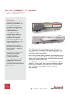
Flex I/O™ and Flex I/O XT™ Modules - Rockwell Automation
configurator.rockwellautomation.com1794-OE8H 24Vdc Selectable Analog 8 Output, with HART pass-thru 1794-OE12 24Vdc Selectable Analog 12 Output Module Isolated Analog I/O Analog Modules 1794-IF4I 24Vdc Source Isolated 4 Input Module 1794-IF4IXT 24Vdc Source Isolated 4 Input Module, XTEMP (-20C to 70C) 1794-IF2XOF2I 24Vdc 2 Input/2 Output Isolated Analog Combo Module

FLEX I/O and FLEX I/O-XT Modules Product Profile
literature.rockwellautomation.com1794-OE8H 24Vdc Selectable Analog 8 Output, with HART pass-thru 1794-OE12 24Vdc Selectable Analog 12 Output Module Isolated Analog I/O Analog Modules 1794-IF4I 24Vdc Source Isolated 4 Input Module 1794-IF4IXT 24Vdc Source Isolated 4 Input Module, XTEMP (-20 °C to 70 °C) 1794-IF2XOF2I 24Vdc 2 Input/2 Output Isolated Analog Combo Module
Radar Transmitter/Receiver - MIT Lincoln Laboratory
www.ll.mit.eduFlex Waveguide Output flanges. Waveguide Harmonic Filter. 200’ antenna waveguide. Water Coolant Hoses, 70 Gal/min. Waveguide output. Varian X780 Klystron • $400,000/tube • 7 ft (height) x 1ft (diameter) • 600 lbs • 3% duty cycle • 42 dB gain • 600W peak input drive level Varian X780 Klystron • $400,000/tube • 7 ft (height) x ...

1794-UM008E-EN-P FLEX I/O Isolated Analog Modules User …
literature.rockwellautomation.comFLEX I/O Input, Output and Input/Output Analog Modules Installation Instructions, publication 1794-IN100 Information on how to install the FLEX I/O Input, Output and Input/Output Analog Modules (Catalog No. 1794-IE8, 1794-IE4XOE2, 1794-OE4, 1794-IE8K, 1794-OE4K). FLEX I/O Analog Module User Manual, publication 1794-UM002

Automotive Diagnostics Communication Protocols Analysis ...
iosrjournals.orgmodules. For example: PCM is to manage Engine and Transmission. Fig 2 presents a block diagram at ECU Managing the Combustion engine.It shows the main input and output signals. Electrical requirements need to be in accordance to the automobile Environment inside the ECU. Figure 2: Engine electronic management with an ECU