
SERVICE MANUAL - Navistar
LoneStar® and ProStar® Chassis Built January, 2007 and After — ELECTRICAL CIRCUIT DIAGRAMS iii 4.44. REMOTE RADIO — N/AMP AND N/WIRED REMOTE AND N/DRIVER INTERFACE DISPLAY,
Download SERVICE MANUAL - Navistar

Information
Domain:
Source:
Link to this page:
Documents from same domain

MaxxForce 11 and 13 (2010) - Navistar
bodybuilder.navistar.comNAV_IST_030711 Idle Shut Down Timer ©2011 Navistar, Inc. MaxxForce 11 and 13 (2010) Overview: Idle Shutdown Timer (including Certified Clean Idle)
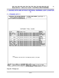
7. GAUGES WITH AND WITHOUT INTEGRAL …
bodybuilder.navistar.com3200, 4100, 4200, 4300, 4400, 7300, 7400, 7500, 7600, 7700, 8500, 8600, MXT, RXT Models Built Oct. 1, 2005 to Feb. 28, 2007 — ELECTRICAL CIRCUIT DIAGRAMS
SERVICE MANUAL - Navistar
bodybuilder.navistar.comservice manual service manual section 3200, 4100, 4200, 4300, 4400, 7300, 7400, 7500, 7600, 7700, 8500, ... eaton voradcollision avoidancesystem,p.23 ...

Component Information 2004 - Navistar
bodybuilder.navistar.comComponent Information 2004 4000 Models Body Builder Data ECM2 Electronic Engine Control Features and Programmable Parameters For International
CF 500, CF 600 Circuit Diagrams - Navistar
bodybuilder.navistar.comIntroduction p 3-5 Component and Connector Information Cell 152 “Component Location Charts” helps the user find where the various items depicted on the schematic can physically be found on the

SERVICE MANUAL SECTION BODY CONTROLLER …
bodybuilder.navistar.comBODY CONTROLLER DIAGNOSTIC TROUBLE CODES (S08327) 1. DEFINITIONS 1.1.2. Displaying Codes on the VID (if equipped) The VID can be used to display all diagnostic trouble codes (DTC) on the vehicle. Suspect parameter number (SPN), failure mode indicator (FMI) and occurrence count numbers are listed. Source addresses and DTC
SERVICE MANUAL - Navistar
bodybuilder.navistar.com3200, 4200, 4300, 4400, 7300, 7400, 7500, 7600, 8500, 8600 SERIES Built After March 10, 2004 — ELECTRICAL CIRCUIT DIAGRAMS i Table of Contents

SERVICE MANUAL - Navistar
bodybuilder.navistar.com4200, 4300, 4400 series built october 16, 2000 to december 31, 2001 — electrical circuit diagrams 1 1. instructions and charts (chapter 1) 1.1. circuit number identification and location chart, p. 1

SERVICE MANUAL
bodybuilder.navistar.com3200, 4200, 4300, 4400, 7300, 7400, 7500, 7600, 8500, 8600 SERIES Built October 1, 2002 and After — ELECTRICAL CIRCUIT DIAGRAMS i Table of Contents

SERVICE MANUAL - Navistar
bodybuilder.navistar.com3200, 4100, 4200, 4300, 4400, 7300, 7400, 7500, 7600, 7700, 8500, 8600, MXT, RXT Models Built Oct. 1, 2005 to Feb. 28, 2007 — ELECTRICAL CIRCUIT DIAGRAMS
Related documents

Power Mobility Devices - CMS
www.cms.govGreater than or equal to 95% of capacity of next lower POV weight class capacity Their home allows adequate POV access between rooms, maneuvering space, and surfaces Using a POV will significantly improve their ability to participate in MRADLs, and they’ll use it at home They haven’t expressed an unwillingness to use a POV at home. PWCs
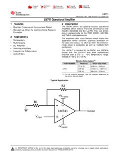
1 Features 3 Description 2 Applications - Texas Instruments
www.ti.comTAMIN ≤TA ≤TAMAX 10 40 Common-mode rejection ratio RSCM = ±12 V, TAMIN ≤TA ≤TAMAX 80 95 dB Supply voltage rejection ratio VS = ±20 V to VS = ±5 V, RSAMIN ≤TA ≤TAMAX 86 96 dB Transient Rise time 0.25 0.8 μs TA = 25°C, unity gain response Overshoot 6% 20% Bandwidth (2) T A = 25°C 0.437 1.5 MHz Slew rate TA = 25°C, unity gain 0 ...
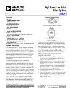
High Speed, Low Noise Video Op Amp Data Sheet AD829
www.analog.comThis op amp is also useful in multichannel, high speed data conversion where its fast (9 0 ns to 0.1%) settling time is important. In such applications, the AD829 serves as an input buffer for 8 -bit to 10-bit ADCs and as an output I/V converter for high speed DACs. CONNECTION DIAGRAM Figure 1. 8-Lead PDIP (N), CERDIP (Q), and SOIC (R)