
SMALL FRAGMENT SYSTEM
• Tapered end for submuscular plate insertion, minimizing tissue trauma Uniform stiffness • Allows smooth contouring of the plate to the bone (Figure 2) • Protects the plate from localized high bending stress, because of the even distribution of stresses over a long distance along the plate Bone loss observed beneath a full-contact plate1, 2
Download SMALL FRAGMENT SYSTEM

Information
Domain:
Source:
Link to this page:
Documents from same domain
CODMAN CERTAS Plus Programmable Valve and …
synthes.vo.llnwd.netProvides the fl exibility, versatility and confi dence to manage the needs of the hydrocephalus patient. CODMAN CERTAS® Plus Programmable Valve and CODMAN CERTAS® Tool Kit ORDERING INFORMATION
LCP Locking Compression Plate - synthes.vo.llnwd.net
synthes.vo.llnwd.netLCP Locking Compression Plate Surgical Technique DePuy Synthes 1 Table of Contents Introduction LCP Locking Compression Plate 2 LCP Metaphyseal Plates 4 AO Principles 5 ...
LCP Locking Compression Plate - synthes.vo.llnwd.net
synthes.vo.llnwd.net4 DePuy Synthes LCP Locking Compression Plate Surgical Technique LCP Metaphyseal Plates. For extra-articular fractures. LCP combi-holes allow uncompromising
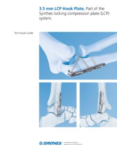
3.5 mm LCP Hook Plate. Part of the Synthes locking ...
synthes.vo.llnwd.netSharp hooks Aid in placement of the plate 3.5 mm LCP Hook Plate. Part of the Synthes locking compression plate (LCP) system. 2 Synthes 3.5 mm LCP Hook Plate Technique Guide

Universal and powerful battery system for a variety …
synthes.vo.llnwd.netColibri II Instructions for Use DePuy Synthes 5 2 Do not reuse Products intended for single use must not be reused. Reuse or reprocessing (e.g. cleaning and resteril-
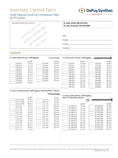
Inventory Control Form - synthes.vo.llnwd.net
synthes.vo.llnwd.netImplants Date: Hospital: Surgeon: Procedure: Case Information (eg, Case ID): Inventory Control Form Small Fragment Locking Compression Plate (LCP®) System 3.5 mm Locking Screws, self-tapping, with StarDriveTM Recess
Inventory Control Form - Limelight Networks
synthes.vo.llnwd.netDate: Hospital: Surgeon: Procedure: Implants Patient Information: J3925-K 6/11 Inventory Control Form Locking Small Fragment–LCP 2.7 mm Cortex Screws,
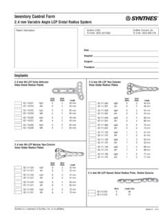
Inventory Control Form - synthes.vo.llnwd.net
synthes.vo.llnwd.netImplants (cont’d) J8493-H 3/13 2.4 mm Cortex Screw, self-tapping, with T8 StarDrive recess Length 201.756 6 mm 201.758 8 mm 201.760 10 mm 201.762 12 mm 201.764 14 mm
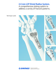
2.4 mm LCP Distal Radius System - Limelight …
synthes.vo.llnwd.net2.4 mm LCP Distal Radius System. A comprehensive plating system to address a variety of fracture patterns. * For long volar plates refer to Synthes Dia-Meta Volar Distal Radius Plate …
For Medial High Tibial Osteotomies TomoFix™ …
synthes.vo.llnwd.netTomoFix Medial High Tibial Plate (MHT) Surgical Technique DePuy Synthes 1 Table of Contents Introduction Indications and Contraindications 4 General Remarks 5 Surgical Technique Open Wedge Surgical Technique 6
Related documents
Gusset Plate Stress 7a - ARC Structural
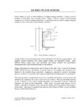
arcstructural.comsection Lw × t, where Lw is the effective width, and t is the plate thickness. The effective width is calculated by assuming the stress spreads through the gusset plate at an angle of 30°. The effective width is shown in Figure 6 for various connection configurations. Fig. 6. Effective width for various connection configurations.

Variable Angle LCP Two-Column Volar Distal Radius Plate 2 ...
synthes.vo.llnwd.netChoose the guiding block corresponding to the desired plate (six or seven head hole configuration, left or right). Mount the guiding block to the plate by turning the guiding block attachment screw clockwise. Note: If using guiding blocks, avoid bending the head portion of the plate. VA locking holes LCP combi-holes

BENDING STRESSES IN BEAMS
crazymech.weebly.comBending in Beams Stresses due to bending Simple Bending or Pure bending Assumptions of theory of Simple Bending ... A steel plate of width 200mm and of thickness 50mm is bent into a circular arc of radius 20m. Determine the max stress induced and the bending moment which will

Bending of plates - iMechanica
imechanica.orgplate we can calculate the bending and twisting moments and the stress distributions. In order to solve this equation, however, we need to know the boundary conditions. In the next section we focus on deriving the proper boundary conditions. 4. The boundary conditions Consider a point on the plate boundary given by x = a. At this point we can ...

Base Plate Verification Example
www.asdipsoft.comDesign the base plate shown in Figure B.4 for an ASD and LRFD required strength of 60 and 90 kips, respectively, and moments from the dead and live loads equal to 480 and 720 kip-in., respectively. The ratio of the concrete to base plate area (A2/A1) is 4.0. Bending is about the strong axis for the

INSTRUCTION MANUAL FOR BRAZED PLATE HEAT …
www.swep.netThe front plate of SWEP BPHEs is marked with an arrow, either on an adhesive sticker or embossed in the cover plate. ... Tension Bending Torque, ½” 3.5 357 2.5 255 20 2 35 3.5 ¾” 12 1224 2.5 255 20 2 115 11.5 1” 11.2 1142 4 408 45 4.5 155 16 1 ¼” 14.5 1479 6.5 663 87.5 9 265 27
Introduction to the Theory of Plates
www.web.stanford.edubending behavior - associated with moment and shear loads applied to the plate’s edges, and transverse loads in the z- direction. Figure See Plate and associated (x, y, z) coordinate system.. depicts a plate and an associated (x, y, z) coordinate system. The top and bottom surfaces lie at z = ±t/2. The flat surface z = 0 is the plate