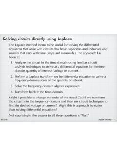
Solving circuits directly using Laplace
Analyze the circuit in the time domain using familiar circuit analysis techniques to arrive at a differential equation for the time-domain quantity of interest (voltage or current). 2. Perform a Laplace transform on the differential equation to arrive a ... C in the RLC circuit below. The input is a step function, v i ...
Download Solving circuits directly using Laplace

Information
Domain:
Source:
Link to this page:
Documents from same domain
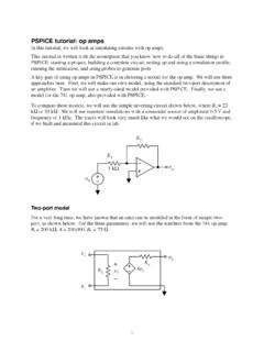
pspice op amp - Iowa State University
tuttle.merc.iastate.eduThis tutorial is written with the assumption that you know how to do ... So it looks like the uA741 model has the potential to be a reasonably accurate PSPICE op amp

How Millennials Can Get Rich Slowly
tuttle.merc.iastate.eduHow Millennials Can Get Rich Slowly William J. Bernstein ©2014 . Would you believe me if I told you that there’s an investment strategy that a seven-year-old could ... and vigor, your retirement options may well range between moving in with your kids and sleeping under a bridge in the rain.
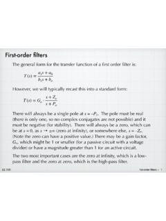
First-order filters - Iowa State University
tuttle.merc.iastate.eduFirst-order filters The general form for the transfer function of a first order filter is: T(s) = G o ... Use the standard definition for cut-off frequency, which is the frequency at which the magnitude is down by from the value in the pass-band. For our low-pass function, the pass band is at low frequencies, and the ...

Basic PMOS structure - Iowa State University
tuttle.merc.iastate.eduohmic or linear v GS < V T v DS < v GS – V T i D = K[v GS – V T]2 saturation Summary of PMOS equations K = 1 2 μCox W L VT < 0 Note the equations are identical to the NMOS equations. For a PMOS, v GS and v DS are both negative and the current flows from source to drain.
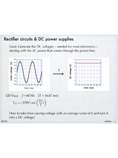
Rectifier circuits & DC power supplies
tuttle.merc.iastate.eduNov 01, 2015 · Rectifier circuits & DC power supplies Goal: Generate the DC voltages – needed for most electronics – starting with the AC power that comes through the power line.? 120 V RMS 9DF=( 9)sin 7 W f = 60 Hz (T = 16.67 ms) How to take time-varying voltage with an average value of 0 and turn it into a DC voltage?
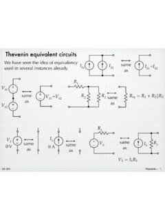
Thevenin equivalent circuits - Iowa State University
tuttle.merc.iastate.eduJun 10, 2014 · The open-circuit voltage / short-circuit current approach can be used to calculate the Thevenin equivalent for a known circuit. Consider the circuit from slide 4: + – V S R 1 R 2 I S 9V 6 mA 1.5 k! 3 k! Open-circuit voltage – Use whatever method you prefer. We’ll use node voltage in this case. + – V S R 1 R 2 I S v a + – v oc YRF= YD ...

Series and parallel combinations
tuttle.merc.iastate.eduEE 201 series/parallel combinations – 12 Breaking down networks using series and parallel R 3 R 4 R 5 R eq R 2 But not all circuits are simple R 1 combinations of series or parallel resistors. The initial example circuit clearly has some things that are in series and some elements that have a parallel-type connection.
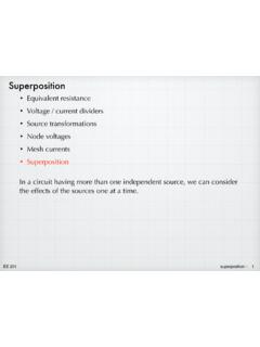
superposition - Iowa State University
tuttle.merc.iastate.eduEE 201 superposition – 2 2va + 6vb = 2V 8va 2vb = 36V Solving gives: v a = 5 V, v b = 2 V 8v a 2v b = 0 2v a + 6v b = 2V Solving gives: and 2v a + 6v b = 0 8v a 2v b = 36V A math problem: Mathematically, we can solve the simultaneous equations a piece at a
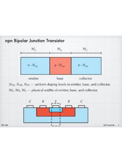
npn Bipolar Junction Transistor - Iowa State University
tuttle.merc.iastate.edujunction — very surprising! EE 436 BJT currents – 6 The electron current in the base is determined by the boundary ... External (terminal) currents. All currents depend on V BE in exactly the same way. Although it is a messy exponential, they …
Diffusion of dopants in silicon - Iowa State University
tuttle.merc.iastate.eduSolid-solubility limit In principle, the surface concentration that shows up in the diffusion expression could be controlled by changing the flow of a gaseous source of the dopant. (More about this later.) In practice, however, N s will be determined by the “solid solubility limit” of the dopant in the silicon. This is the thermodynamic ...
Related documents
Circuits RC, RL, RLC - gilbert.gastebois.pagesperso-orange.fr
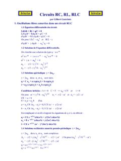
gilbert.gastebois.pagesperso-orange.frCircuits RC, RL, RLC par Gilbert Gastebois 1. Oscillations libres amorties dans un circuit RLC 1.1 Équation différentielle du circuit. Ldi/dt + Ri + q/C = 0
RLC Resonant Circuits - University of Cambridge
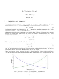
mlg.eng.cam.ac.ukowing in the circuit, however for a parallel RLC circuit this will not be the same. Similarly, V Crms is the rms voltage across the capacitor. For the simple parallel RLC circuit shown in gure 5 this is just equal to the rms supply voltage but for the …

State Space Approach to Solving RLC circuits
web.mit.edu– Solve RLC circuit for i 1(t) and i 2(t) using the node or loop method • We will use node method in our examples • Note that the equations at e 1 and e 2 give us i 1 and i 2 directly in terms of e 1, e 2, e 3 – Also note that v 1 = e 1 and v 2 = e 2 – Equation at e 3 gives e 3 in terms of e 1 and e 2 We!have, d dt v 1 (t)= i 1 (t) C ...

11. The Series RLC Resonance Circuit
www.hunter.cuny.edu11. The Series RLC Resonance Circuit Introduction Thus far we have studied a circuit involving a (1) series resistor R and capacitor C circuit as well as a (2) series resistor R and inductor L circuit. In both cases, it was simpler for the actual experiment to replace the battery and switch with a signal generator producing a square wave.

RLC Circuit - Iowa State University
apps-dso.sws.iastate.eduRLC Circuit: Phasors: ALWAYS draw the diagram!! 22 22 () tan L C LRC L C Z X X R E V V V E IZ XX R M Related Problems 1) You have a 200 ohm resistor, a 0.400-H inductor. Suppose you take the resistor and inductor and make a series circuit with a voltage source that has voltage amplitude 30.0 V

RC snubber circuit design for TRIACs - STMicroelectronics
www.st.comAN437 How to design snubber circuit for turn-off improvement 7/18 2 How to design snubber circuit for turn-off improvement 2.1 Step response of an RLC series circuit The RSCS snubber circuit makes up a resonant circuit with an inductive load (refer L and R on Figure 7). At turn-off, the snubber circuit limits the slope of the reapplied voltage