
Wire Harness Installation Instructions - Painless Performance
Installation requires four (4) easy steps: 1. Mount the fuse block 2. Route the wires 3. Cut off the excess wire 4. Terminate the wires 2.0 ABOUT THESE INSTRUCTIONS The contents of these instructions are divided into major Sections, as follows: 1.0 Introduction 2.0 About These Instructions 3.0 Tools Needed
Download Wire Harness Installation Instructions - Painless Performance

Information
Domain:
Source:
Link to this page:
Documents from same domain

Manual #90567 For Installing: Part #30830
www.painlessperformance.com7 Figure 1 C.S.I. Harness Schematic CONTENTS OF THE PAINLESS C.S.I. WIRE HARNESS KIT Refer to the list below to take inventory of all the parts in the kit. If anything is found to be
For Installing: #10127 Customizable Mopar Chassis …
www.painlessperformance.comWire Harness Installation Instructions For Installing: #10127 Customizable Mopar Chassis Harness 21 Circuit Manual #90542

Wire Harness Installation Instructions - Painless …
www.painlessperformance.comWire Harness Installation Instructions For Installing: #20110 Classic Customizable Chevy II/Nova 1966-67 Harness 21 Circuit Manual #90522

Wire Harness Installation Instructions - Painless …
www.painlessperformance.comWire Harness Installation Instructions For Installing: Part #20120 22 Circuit Ford Mustang (1965- 1966) Manual #90526

Wire Harness Installation Instructions - Painless …
www.painlessperformance.comWire Harness Installation Instructions For Installing: #10101 Classic Customizable Harness-GM Keyed Column-21 Circuit #10102 Classic Customizable Harness-Non GM Keyed Column-21 Circuit

175 o OFF THERMOSTAT INSTALLATION …
www.painlessperformance.com1 2501 Ludelle Street Fort Worth, Texas 76105 . 817-244-6212 phone . 817-244-4024 fax . 800-423-9696 Tech . E-Mail: painless@painlessperformance.com . Web: www.painlessperformance.com

Manual #90560 For Installing: #10111 Direct Fit Jeep YJ ...
www.painlessperformance.com7 Sections are divided into subsections and Paragraphs.Throughout these instructions, the Figure numbers refer to pictures and the Diagram numbers refer to illustrations.Figure numbers correspond to the Section number the are covered in. Always pay special and careful

HIGH AMPERAGE ALTERNATOR KIT (140-190 AMPS)
www.painlessperformance.com2 onto the output post of the alternator. This connection can be seen in Figure 1 on the next page and can be accomplished one of two ways: #1 Install each wire separately • Slide the rubber boot and/or a piece of the smaller sized heat shrink onto the wire found in the kit.

Wire Harness Installation Instructions
www.painlessperformance.com3.0 CONTENTS OF THE PAINLESS WIRE HARNESS KIT Refer to the list below to take inventory of all the parts in the kit. If anything is found to be missing, contact the dealer the kit was purchased

80230 - painlessperformance.com
www.painlessperformance.comPainless Performance Limited Warranty and Return Policy Chassis harnesses and fuel injection harnesses are covered under a lifetime warranty. All other products manufactured and/or sold by Painless Performance
Related documents

CENTRAL BOILER OUTDOOR FURNACE INSTALLATION AND …
centralboiler.comthe unit, unless the installation of a spark arrester is prohibited by local requirements. Use common sense to avoid potential fires, including exercising caution when disposing of ashes, cleaning and refueling. Keep all highly combustible materials (e.g., gasoline, propane, leaves, pine needles, etc.) away from an operating unit at all times.

Kinetix 5500 Servo Drives Installation Instructions
literature.rockwellautomation.com• These installation instructions, publication 2198-IN001 Remove the Grounding Screws in Ungrounded Power Configurations Remove the grounding screws only when using ungrounded, corner-grounded, or impedance-grounded power configurations. Removing t he screws involves gaining access, opening the side door, and removing the screws.

INSTALLATION INSTRUCTIONS - Fisher & Paykel
www.fisherpaykel.com4 3 PrOdUCt diMeNSiONS tOP Side PrOdUCt diMeNSiONS mm A Overall height1 of product 820-8802 B Overall width of product 599 C Overall depth of product 582 D Depth of chassis (to back of front panel) 553 E Maximum extension of drawer 556 F Depth of front panel 29 G Height1 of chassis 811 H Height of levelling feet 9-692 I Height of drawer fronts 711 J Height of upper …

Owner’s Manual & Safety Instructions
manuals.harborfreight.comE rati O n Maint E nanc E S E tup 6. Handle solar panel with care, edges may be sharp. 7. Do not focus light on panel. 8. install components with enough space to allow proper cooling. 9. this product may occasionally produce more current and/or voltage than its rated output. increase output ratings by 25% when determining component required voltage

INSTALLATION INSTRUCTIONS - FREESTANDING GAS …
pdf.lowes.comthe gas supplier's instructions. • If you cannot reach your gas supplier, call the fire department. — Installation and service must be performed by a qualified installer, service agency or the gas supplier. Important notes to the installer • Read all instructions contained in these installation instructions before installing range.
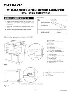
24 Flush Mount DeFlector Vent: sKMD24F0As
files.sharpusa.comE 1 C N H E F D A B L J I M K G Note: the face of the shelf must sit 1 3/4" (44.45 mm) back from ... INSTALLATION INSTRUCTIONS 1. Prepare cabinet opening as shown in Figures 1, 2A, 2B, 2C. CL Top view A Anti-Tip block Mounting cleat Drawer face B C Cabinet face Note: the mounting surface of the finished cleat must sit 1 1/16" (26.97 mm) back