
ZedBoard HW Users Guide - Digilent Reference
Aug 01, 2012 · Hardware User’s Guide Version 1.1 August 1st, 2012 . 1 1-Aug-2012 ... o USB-JTAG Programming using Digilent SMT1-equivalent circuit Accesses PL JTAG ... The PCB design guidelines outlined in Zynq datasheet must be followed for trace matching, etc. Table 1 - DDR3 Connections ...
Download ZedBoard HW Users Guide - Digilent Reference

Information
Domain:
Source:
Link to this page:
Documents from same domain
Nexys4 DDR™ FPGA Board Reference Manual - Digilentinc
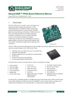
digilent.comType A USB Host Connector (J5) Serial Prog. Port 2 6-pin JTAG Header (J10) Prog Micro SD Connector (J1) Media Select (JP2) User I/O M2 Mode (JP 1) Programming Mode JP2 JP1 NA SPI Flash NA JTAG USB MicroSD Figure 3. Nexys4 DDR configuration options. Figure 3 shows the different options available for configuring the FPGA. An on-board “mode ...
Basys 3™ FPGA Board Reference Manual - Digilent Reference
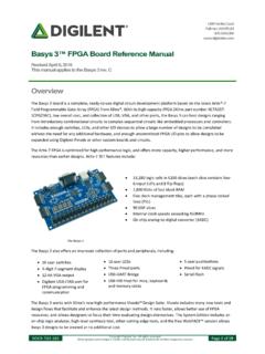
digilent.comPIC24 Type A USB Host Connector (J2) Serial Prog. Port 2 6-pin JTAG Header (J5) Prog M2 Mode (JP1) Programming Mode JP1 SPI Flash JTAG USB Figure 3. Basys 3 configuration options. The FPGA configuration data is stored in files called bitstreams that have the .bit file extension. The Vivado

Nexys A7 FPGA Board Reference Manual - Digilentinc
digilent.comThe major improvement from the Nexys 4 to the Nexys 4 DDR is the replacement of the 16 MiB Cellular RAM with a 128 MiB DDR2 SDRAM memory. Furthermore, to accommodate the new memory, the pin-out of the FPGA banks changed as well. The audio output (AUD_PWM) needs to be driven open-drain as opposed to push-pull on the Nexys 4. 1 Functional Description

Zybo Z7 Board Reference Manual - Digilentinc
digilent.com• High-bandwidth peripheral controllers: 1G Ethernet, USB 2.0, SDIO • Low-bandwidth peripheral controllers: SPI, UART, CAN, I2C • Programmable from JTAG, Quad-SPI flash, and microSD card • Programmable logic equivalent to Artix-7 FPGA

Arty™ FPGA Board Reference Manual - Digilent Reference
digilent.comport (J10) or it can be derived from a 7 to 15 Volt D power supply that [s connected to Power Jack (J12) or Pin 8 of Header J7. Header J13, located between the power jack and the Ethernet connector, is used to determine which source is used. A power-good LED (LD11), driven by the power good _ (PWRGD) output of the ADP5052 regulator, indicates that

Analog Discovery ™ Technical Reference Manual
digilent.com• Spectrum Analyzer - power spectrum and spectral measurements (noise floor, SFDR, SNR, THD, etc.) • Digital Bus Analyzers (SPI, I2C, UART, Parallel) Figure 1. The Analog Discovery. Features include:

ZYBO - Digilentinc
digilent.comMay 31, 2017 · zybo z7 board digilen t inc. a vailable on z20 v er sion only pibtn401 pibtn402 pibtn403 cobtn4 pibtn404 pibtn501 pibtn502 pibtn503 cobtn5 pibtn504 pid101 pid102 pid103 pid104 pid105 cod1 pid201 pid202 pid203 pid204 pid205 cod2 pid301 pid302 pid303 pid304 pid305 cod3 pid401 pid402 pid403 pid404 pid405 cod4 ...

Analog Discovery 2™ Reference Manual
digilent.comStereo audio amplifier to drive external headphones or speakers with replicated AWG signals 16-channel pattern generator (3.3V CMOS, 100Msample/sec)i ii 16-channel virtual digital I/O including buttons, switches, and LEDs – perfect for logic training applicationsiii iv 16-channel digital logic analyzer (3.3V CMOS,

Digilent Pmod Interface Specification
digilent.comhost controller boards. There are six-pin and twelve-pin versions of the interface defined. The six-pin ... Microcontroller system boards are generally provided with dedicated I 2C connectors and provide pull-up resistors that are jumper selectable to be in or out of circuit. FPGA based system boards generally

Introduction to Digital Design Using Digilent FPGA Boards
digilent.comExample 9 – 7-Segment Decoder 48 Example 10 – 7-Segment Displays: x7seg and x7segb 54 Example 11 – 2's Complement 4-Bit Saturator 64 Example 12 – Full Adder 70 ... digital circuit and implement it by connecting the internal gates in a particular way. This
Related documents
Dell OptiPlex 3060 Micro Service Manual
dl.dell.comUSB features. Universal Serial Bus, or USB, was introduced in 1996. It dramatically simplified the connection between host computers and peripheral devices like mice, keyboards, external drivers, and printers. Table 1. USB evolution . Type Data Transfer Rate Category Introduction Year. USB 2.0 480 Mbps High Speed 2000. 8 Technology and components
BM83 Bluetooth® Stereo Audio Module DS
ww1.microchip.com• UART (With Hardware Flow Control) • USB (Full-Speed USB 1.1 Interface) • Inter-Integrated Circuit (I2C™) Host • One Pulse Width Modulation (PWM) Channel • Two LED Drivers • Up to 18 General Purpose Inputs/Outputs (GPIOs) • 2-wire 8051 MCU Joint Test Action Group (JTAG) Debug Operating Conditions • Operating Voltage: 3.2V to 4.2V
AN0046: USB Hardware Design Guidelines
www.silabs.comAN0046: USB Hardware Design Guidelines This application note gives recommendations on hardware design for implementing USB host and device applications using USB capable EFM32 microcontrollers along with some example schematics for different applications. KEY POINTS • Example Schematics for a variety of applications • PCB Design Guidelines ...
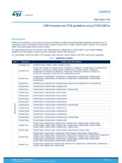
USB hardware and PCB guidelines using STM32 MCUs ...
www.st.comThis application note gives an overview of the USB peripherals implemented on STM32 MCUs, and provides hardware guidelines for PCB design, to ensure electrical compliance with the USB standards. For more details, refer to the USB or OTG sections in the reference manual related to the MCU used for your application.
STM32Cube USB Host Library STMicroelectronics ...
www.st.comIt allows using an STM32 microcontroller as an USB embedded host for communication with USB peripherals of various USB classes (MSC, HID, CDC, Audio and MTP). Note: This document is applicable to all STM32 series that feature an USB OTG peripheral.

X9SCM X9SCM-F X9SCL X9SCL-F X9SCL+-F
www.supermicro.comChapter 2 provides hardware installation instructions. Read this chapter when in-stalling the processor, memory modules and other hardware components into the system. If you encounter any problems, see Chapter 3, which describes trouble-shooting procedures for video, memory and system setup stored in the CMOS.