Transcription of 7. COGENERATION - Bureau of Energy Efficiency
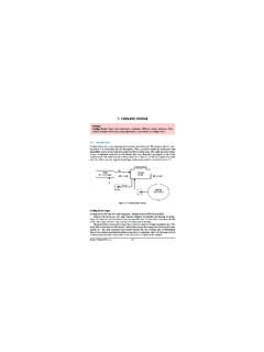
1 7. COGENERATION155 Bureau of Energy EfficiencySyllabus COGENERATION : Definition, Need, Application, Advantages, Classification, Saving Need for CogenerationThermal power plants are a major source of electricity supply in India. The conventionalmethod of power generation and supply to the customer is wasteful in the sense that only abouta third of the primary Energy fed into the power plant is actually made available to the user inthe form of electricity (Figure ). In conventional power plant, Efficiency is only 35% andremaining 65% of Energy is lost. The major source of loss in the conversion process is the heatrejected to the surrounding water or air due to the inherent constraints of the different thermodynamic cycles employed in power generation.
2 Also further losses of around 10 15%are associated with the transmission and distribution of electricity in the electrical Principle of CogenerationCogeneration or Combined Heat and Power (CHP) is defined as the sequential generation oftwo different forms of useful Energy from a single primary Energy source, typically mechanicalenergy and thermal Energy . Mechanical Energy may be used either to drive an alternator for pro-ducing electricity, or rotating equipment such as motor, compressor, pump or fan for deliveringFigure BALANCE IN TYPICAL COAL FIRED POWER STATION For an Input Energy of 100 Giga Joules (GJ) 2/23/2005 11:24 AM Page 155various services.
3 Thermal Energy can be used either for direct process applications or for indi-rectly producing steam, hot water, hot air for dryer or chilled water for process provides a wide range of technologies for application in various domains ofeconomic activities. The overall Efficiency of Energy use in COGENERATION mode can be up to 85per cent and above in some cases. For example in the scheme shown in Figure , an industry requires 24 units of electricalenergy and 34 units of heat Energy . Through separate heat and power route the primary energyinput in power plant will be 60 units (24 ). If a separate boiler is used for steam generationthen the fuel input to boiler will be 40 units (34 ).
4 If the plant had COGENERATION then thefuel input will be only 68 units (24+34) to meet both electrical and thermal Energy requirements. It can be observed that the losses, which were 42 units in the case of, separateheat and power has reduced to 10 units in COGENERATION with the saving of fossil fuels, COGENERATION also allows to reduce the emission ofgreenhouse gases (particularly CO2emission). The production of electricity being on-site, theburden on the utility network is reduced and the transmission line losses makes sense from both macro and micro perspectives.
5 At the macro level, itallows a part of the financial burden of the national power utility to be shared by the private sector; in addition, indigenous Energy sources are conserved. At the micro level, the overallenergy bill of the users can be reduced, particularly when there is a simultaneous need for bothpower and heat at the site, and a rational Energy tariff is practiced in the Technical Options for COGENERATION COGENERATION technologies that have been widely commercialized include extraction/backpressure steam turbines, gas turbine with heat recovery boiler (with or without bottoming steamturbine) and reciprocating engines with heat recovery boiler.
6 7. Cogeneration156 Bureau of Energy Efficiency Figure COGENERATION 2/23/2005 11:24 AM Page Steam turbine COGENERATION systems The two types of steam turbines most widely used are the backpressure and the extraction-Another variation of the steam turbine topping cycle COGENERATION system is the extraction-backpressure turbine that can be employed where the end-user needs thermal Energy at two different temperature levels. The full-condensing steam turbines are usually incorporated atsites where heat rejected from the process is used to generate power. The specific advantage of using steam turbines in comparison with the other prime moversis the option for using a wide variety of conventional as well as alternative fuels such as coal,natural gas, fuel oil and biomass.
7 The power generation Efficiency of the emand for electricityis greater than one MW up to a few hundreds of MW. Due to the system inertia, their operationis not suitable for sites with intermittent Energy demand. Gasturbine COGENERATION Systems Gas turbine COGENERATION systems can produce all or a part of the Energy requirement of the site,and the Energy released at high temperature in the exhaust stack can be recovered for variousheating and cooling applications (see Figure ). Though natural gas is most commonly used,other fuels such as light fuel oil or diesel can also be employed. The typical range of gas turbines varies from a fraction of a MW to around 100 MW.
8 Gas turbine COGENERATION has probably experienced the most rapid development in therecent years due to the greater availability of natural gas, rapid progress in the technology, significant reduction in installation costs, and better environmental performance. Furthermore,the gestation period for developing a project is shorter and the equipment can be delivered in amodular manner. Gas turbine has a short start-up time and provides the flexibility of intermit-tent operation. Though it has a low heat to power conversion Efficiency , more heat can be recovered at higher temperatures .
9 If the heat output is less than that required by the user, it ispossible to have supplementary natural gas firing by mixing additional fuel to the oxygen-richexhaust gas to boost the thermal output more Cogeneration157 Bureau of Energy EfficiencyFigure Schematic Diagrams of Steam turbine COGENERATION 2/23/2005 11:24 AM Page 157On the other hand, if more power is required at the site, it is possible to adopt a combined cyclethat is a combination of gas turbine and steam turbine COGENERATION . Steam generated from theexhaust gas of the gas turbine is passed through a backpressure or extraction-condensing steamturbine to generate additional power.
10 The exhaust or the extracted steam from the steam turbineprovides the required thermal Reciprocating Engine COGENERATION Systems Also known as internal combustion (I. C.) engines, these COGENERATION systems have high powergeneration efficiencies in comparison with other prime movers. There are two sources of heatfor recovery: exhaust gas at high temperature and engine jacket cooling water system at lowtemperature (see Figure ). As heat recovery can be quite efficient for smaller systems, thesesystems are more popular with smaller Energy consuming facilities, particularly those having agreater need for electricity than thermal Energy and where the quality of heat required is nothigh, low pressure steam or hot Cogeneration158 Bureau of Energy EfficiencyFigure Schematic Diagram of Gas turbine CogenerationFigure Schematic Diagram of Reciprocating Engine CogenerationFlueGases( 500 C)ExhaustHeat( 150 C)WaterBoilerFuel AirGas 2/23/2005 11.