Transcription of EJA210E Flange Mounted Differential Pressure Transmitter
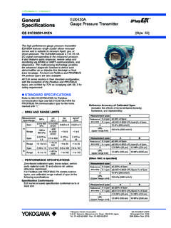
1 GeneralSpecifications<<Contents>> <<Index>>EJA210 EFlange MountedDifferential Pressure TransmitterYokogawa Electric Corporation2-9-32, Nakacho, Musashino-shi, Tokyo, 180-8750 JapanTel.: 81-422-52-5690 Fax.: 81-422-52-2018GS 01C31C01-01 ENGS 01C31C01-01EN Copyright June 201212th Edition June 2017 The high performance Flange Mounted Differential Pressure Transmitter EJA210E can be used to measure levels of densities of solidifying or precipitating liquids. EJA210E outputs a 4 to 20 mA DC signal corresponding to the measured Differential Pressure .
2 Its accurate and stable sensor can also measure the static Pressure which can be shown on the integral indicator or remotely monitored via BRAIN or HART communications. Other key features include quick response, remote set-up using communications and self-diagnostics. FOUNDATION Fieldbus, PROFIBUS PA and 1 to 5 V DC with HART (Low Power) protocol types are also available. All EJA-E series models in their standard configuration, with the exception of the Fieldbus, PROFIBUS and Low Power types, are certified as complying with SIL 2 for safety requirement.
3 STANDARD SPECIFICATIONSR efer to GS 01C31T02-01EN for Fieldbus communication type and GS 01C31T04-01EN for PROFIBUS PA communication type for the items marked with . SPAN AND RANGE LIMITSM easurementSpan/RangekPainH2O(/D1)mbar(/D 3)mmH2O(/D4)MSpan1 to 1004 to 40010 to 1000100 to 10000 Range-100 to 100-400 to 400-1000 to 1000-10000 to 10000 HSpan5 to 50020 to 200050 to to 5 kgf/cm2 Range-500 to 500-2000 to 2000-5000 to 5000-5 to 5 kgf/cm2 PERFORMANCE SPECIFICATIONSZero-based calibrated span, linear output, wetted parts material code SW for 3-inch Flange flush type, and fill fluid code Fieldbus and PROFIBUS PA communication types.
4 Use caribrated range instead of span in the following ConformanceEJA-E series ensures specification conformance to at least 3 .Reference Accuracy of Calibrated Span(includes terminal-based linearity, hysteresis, and repeatability)Measurement spanMReferenceaccuracyX span of SpanX > span ( + URL/span)% of SpanX10 kPa (40 inH2O)URL(upper range limit)100 kPa (400 inH2O)Measurement spanHReferenceaccuracyX span of SpanX > span ( + URL/span)% of SpanX100 kPa (400 inH2O)URL(upper range limit)500 kPa (2000 inH2O)Ambient Temperature Effects per 28 C (50 F) ChangeCapsuleEffectMH ( Span+ URL) ( Span+ URL)
5 Static Pressure Effects per MPa (100 psi) Change Span EffectsM and H capsules of span Effect on ZeroM and H capsules of URLS tability % of URL per 12 monthsPower Supply Effects(Output signal code D and J) % per Volt (from to 32 V DC, 350 )Response Time ( Differential Pressure ) M and H capsule: 120 ms (approximate value at normal temperature)When software damping is set to zero and including dead time of 45 ms (nominal)2 All Rights Reserved. Copyright 2012, Yokogawa Electric Corporation<<Contents>> <<Index>>GS 01C31C01-01 ENStatic Pressure Signal Range and Accuracy (For monitoring via communication or on indicator for BRAIN and HART communication type.)
6 Includes terminal-based linearity, hysteresis, and repeatability) RangeUpper Range Value and Lower Range Value of the static Pressure can be set in the range between 0 and Maximum Working Pressure (MWP*). The upper range value must be greater than the lower range value. Minimum setting span is MPa (73 psi). * : Maximum Working Pressure (MWP) is within Flange rating Pressure . AccuracyAbsolute Pressure1 MPa or higher: of spanLess than 1 MPa: (1 MPa/span) of spanGauge Pressure ReferenceGauge Pressure reference is 1013 hPa (1 atm)Note: Gauge Pressure variable is based on the above fixed reference and thus subject to be affected by the change of atomospheric Pressure .
7 FUNCTIONAL SPECIFICATIONSO utput For 4 to 20 mA HART / BRAIN (Output signal code D and J)Two wire 4 to 20 mA DC output with digital or HART FSK protocol are superimposed on the 4 to 20 mA range: mA to mAOutput limits conform to NAMUR NE43 can be preset by option code C2 or 1 to 5 V HART (Output signal code Q)Three or four wire low power 1 to 5 V DC output with HART, linear or square root programmable. HART protocol are superimposed on the 1 to 5 V DC range: V to V DCFailure Alarm For 4 to 20 mA HART / BRAIN (Output signal code D and J)Output status at CPU failure and hardware error;Up-scale: 110%, mA DC or more (standard)Down-scale: 5%, mA DC or lessFor 1 to 5 V HART (Output signal code Q)Analog output status at CPU failure and hardware error.
8 Up-scale: 110%, V DC or more (standard) Down-scale: 5%, V DC or lessDamping Time Constant (1st order)Amplifier damping time constant is adjustable from to s by software and added to response : For BRAIN protocol type, when amplifier software damping is set to less than s, communication may occasionally be unavailble during the operation, especially while output changes dynamically. The default setting of damping ensures stable Period Differential Pressure : 45 msStatic Pressure : 360 msZero Adjustment LimitsZero can be fully elevated or suppressed, within the lower and upper range limits of the Zero AdjustmentExternal zero is continuously adjustable with incremental resolution of span.
9 Re-range can be done locally using the digital indicator with rangesetting Indicator (LCD display, optional) 5-digit numerical display, 6-digit unit display and bar indicator is configurable to display one or up to four of the following variables periodically.;Measured Differential Pressure , Differential Pressure in %, scaled Differential Pressure , measured static Pressure . See also Factory Setting. Local Parameter Setting (Output signal code D, J and Q)Parameter configuration by the external zero adjustment screw and push button (Integral indicator code E) offers easy and quick setup for parameters of Tag number, Unit, LRV, URV, Damping, Output mode (linear/square root), Display out 1, and Re-range by applying actual Pressure (LRV/URV).
10 Self DiagnosticsCPU failure, hardware failure, configuration error, process alarm for Differential Pressure , static Pressure or capsule process high/low alarm for Differential Pressure and static Pressure is also Characterizer (Output signal code D, J and Q)User-configurable 10-segment signal characterizer for 4 to 20 mA CertificationEJA-E series transmitters except Fieldbus, PROFIBUS PA and 1-5V DC with HART (Low Power) communication types are certified in compliance with the following standards;IEC 61508: 2010; Part1 to Part 7 Functional Safety of Electrical/electronic/programmable electronic related systems; SIL 2 capability for single Transmitter use, SIL 3 capability for dual Transmitter use.