Transcription of Parallel Type Air Gripper/2 Finger, 3 Finger, 4 Finger
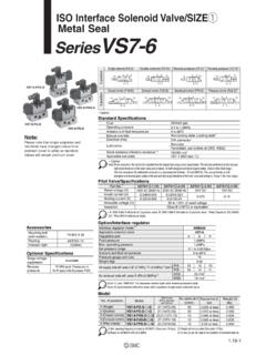
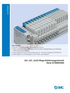
1 MHS SeriesParallel Type Air Gripper/2 Finger , 3 Finger , 4 Finger 16, 20, 25, 32, 40, 50, 63, 80, 100, 125569 MHZMHFMHLMHRMHKMHSMHCMHTMHYMHW-X MRHQMAD- MHSL ightweight, compact design with reduced heightBore size (mm) series Variations1620253240506380 100 125 Smaller auto switch mountableSmaller auto switchesD-M9 (V)D-M9 W(V)D-M9 A(V) tapped holes Using through holesCan be mounted from two directionsEasy alignment when mountingPositioning pin holes are provided on the top of the switch capableA wide variety of solid state auto switches can bemounted using the body s side mounting include 2-color indication and water resistant repeatability.
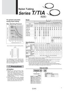
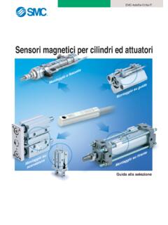
2 MmEmploys wedge cam constructionThe wedge cam mechanism allows strong gripping forceto be obtained from a compact SeriesMHS3 SeriesMHS4 SeriesGripping of diverseworkpiecesAxial gripping ofcylindrical workpiecesPositioning of square workpiecesAccommodates a wide rangeof workpiece diametersLong stroke MHSL3 Series570 Ideal for gripping workpieces of different diametersMHS3 VariationsMHSL3 Long StrokeWith dust cover/Center pusherThe dust cover and center pusher assembly can be modularized for the through-hole 20 25 32 40 50 63 80 Bore size (mm)MHSJ3 MHSH3 MHSHJ3 Opening/Closing stroke more than twice the standard (MHS3) 10 (4)10 (4)12 (6)16 (8)20 (8)28 (12)32 (16)40 (20)48 (24)64 (32)Stroke (mm)Dia.
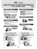
3 : Open ClosedHeight(mm)Weight(g)801351803705509 301,5502,8505,50011,300 135 175 Bore size(mm)1620253240506380100125 Standard inside ( )/MHS3 strokeGripping of differentdiameter coverSpring typeCylinder typeThrough-holeMHSH3 Center pusher assembly The mounting pitch is compatiblewith the standard acting/MHS3-X84 With dust 16, 20, 25, 32, 40, 50, 63 Single acting/Normally open: External gripSingle acting/Normally closed: Internal gripSymbolAir blowingPushing out a workpiece with external cylinder MHS3-X84 With dust cover Through-holeWith center pusher (Cylinder type) With center pusher (Spring type) Through-hole with dust coverWith dust cover/Center pusher (Cylinder type) With dust cover/Center pusher (Spring type)Single acting (Normally open, Normally closed)
4 571 MHZMHFMHLMHRMHKMHSMHCMHTMHYMHW-X MRHQMAD- MHSS eries VariationsSeriesActionBore size [mm]1620253240506380100125 MHS3 Double actingV V V V V V V V V VSingle actingNormally openV V V V V V V Normally closed 16, 20, 25, 32, 40, 50, 63 Added single acting (Made to Order -X84) to3- Finger type (MHS3 series ).Top portSide portAuto switch wiringAir pipingNormally open or normally closed type can be position can be changed according to installation piping can be connected from the side port or top port of the body, which allows for improved piping and auto switch wiring entries are one way. (For top ported)Space reduced through integration of air piping and auto switch SelectionWorkpiece mass: kgGripping point: 20 mmOperating pressure: MPaExampleGripping method: External grippingSelection ProcedureNumber of fingers.
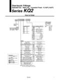
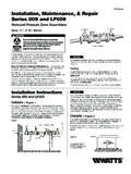
5 2 Model MPaConfirmation of conditionsCalculation of required gripping forceSelection of model from gripping force graphConfirmation of Gripping ForceConfirmation of gripping forceConfirmation of gripping pointStep 1 Step 2 Step 1 Model selection criteria with respect to workpiece weight Although differences will exist depending on the coefficient of friction between attachments and workpieces, select a model which will provide a gripping force as shown in the table 1) Refer to the model selection illustration regarding multiples of the workpiece weight. If high acceleration, deceleration or impact forces are encountered during motion, a further margin of safety should be ) When it is desired to set the gripping force at 20 times or more above the workpiece gripping force= kg x 20 x m/s2 N or moreMultiples of gripping force by workpiece weight10 to 20 times or more7 to 13 times or more5 to 10 times or moreMHS2-32 DExternal Gripping ForcePressure MPaGripping point L (mm)Gripping force (N) Selecting the gripping force of 92 N is obtained from the intersection point of the gripping point distance L = 20 mm and a pressure of MPa.
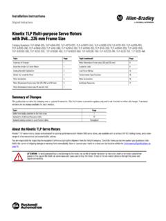
6 The gripping force is 23 times greater than the workpiece mass, and therefore satisfies a gripping force setting value of 20 times or ) For , refer to the gripping point for the effective gripping force of each 2 MHS SeriesModel Selection574 Model Selection IllustrationFFm x gWhen gripping a workpiece as in the figure to the left, and with the following definitions,n: Number of fingersF: Gripping force (N) : Coefficient of friction between attachments and workpiecem: Workpiece mass (kg)g: Gravitational acceleration (= m/s2) mg: Workpiece weight (N)the conditions under which the workpiece will not drop aren x F > mgand therefore, mgF > n x With a as the safety margin, F is determined as follows: a x mgF = n x Multiples of Gripping Force by Workpiece MassNumber of fingers: When n = 2 SMC performs calculations allowing for impacts which occur during normal transfer, etc.
7 , using a safety margin of a = x workpiece weight20 x workpiece weightNote) Even in cases where the coefficient of friction is greater than = , for safety reasons, SMC recommends selecting a gripping force which is at least 10 to 20 times the workpiece weight. If high acceleration, deceleration or impact forces are encountered during motion, a further margin of safety should be SeriesParallel Type Air Gripper2 Finger , 3 Finger , 4 FingerWhen = = mgF = x 4 2 x = 10 x mg mgF = x 4 2 x = 20 x mg x F x F 575 MHZMHFMHLMHRMHKMHSMHCMHTMHYMHW-X MRHQMAD- MHSP arallel Type Air Gripper/2 - Finger TypeMHS2 series 16, 20, 25, 32, 40, 50.
8 63 Bore size 16 to 25M9BW20 MHS2D2 of auto switchesNilS2 of auto switchesNilS2 fingersNumber of fingers22 fingersNumber of fingers216 mm20 mm25 mmBore size162025 ActionDouble actingDAuto switchNilWithout auto switch (Built-in magnet) 32 to 63M9 BWMHS2D50 ActionBore sizeBore size32 mm40 mm50 mm63 mm32405063 For the applicable auto switch model, refer to the table switchNilWithout auto switch (Built-in magnet) For the applicable auto switch model, refer to the table Auto Switches/Refer to pages 797 to 850 for further information on auto Auto Switches/Refer to pages 797 to 850 for further information on auto switches. Load voltageDC24 V12 V12 VACLead wire length (m) (Nil)1 (M) 3 (L)M9 NVM9 PVM9 BVM9 NWVM9 PWVM9 BWVM9 NAV M9 PAV M9 BAV Auto switch modelM9NM9PM9BM9 NWM9 PWM9 BWM9NA M9PA M9BA 5 (Z)5 V,12 V5 V,12 V 12 V5 V,12 VTypeSolid state auto switchSpecialfunctionElectricalentryIndi catorlightWiring(Output)Diagnosis(2-colo r indicator)Water resistant(2-color indicator)GrommetYes3-wire (NPN) 3-wire (PNP) 3-wire (PNP) 2-wire3-wire (NPN) 3-wire (PNP) 2-wire2-wire3-wire (NPN) Pre-wiredconnectorApplicableloadRelay,PL CIC circuitICcircuitICcircuitIn-linePerpendi cularNote)
9 When using the 2-color indicator type, please make the setting so that the indicator is lit in red to ensure the detection at the proper position of the air gripper. Water resistant type auto switches can be mounted on the above models, but in such case SMC cannot guarantee water actingD Load voltageDC24 V12 V12 VACLead wire length (m) (Nil)1 (M) 3 (L)M9 NVM9 PVM9 BVM9 NWVM9 PWVM9 BWVM9 NAV M9 PAV M9 BAV Auto switch modelM9NM9PM9BM9 NWM9 PWM9 BWM9NA M9PA M9BA 5 (Z)5 V,12 V5 V,12 V12 V5 V,12 VTypeSolid state auto switchSpecialfunctionElectricalentryIndi catorlightWiring(Output)Diagnosis(2-colo r indicator)Water resistant(2-color indicator)GrommetYes3-wire (NPN) 3-wire (PNP) 3-wire (PNP) 2-wire3-wire (NPN) 3-wire (PNP) 2-wire2-wire3-wire (NPN)
10 Pre-wiredconnectorApplicableloadRelay,PL CIC circuitICcircuitICcircuitIn-linePerpendi cularMade to Order Refer to page 577 for to Order Refer to page 577 for 1) When using the 2-color indicator type, please make the setting so that the indicator is lit in red to ensure the detection at the proper position of the air 2) When ordering the air gripper with auto switch, auto switch mounting brackets are supplied with the air gripper having a bore size of 32 to 3) When ordering the auto switch separately, auto switch mounting brackets (BMG2-012) are required. Water resistant type auto switches can be mounted on the above models, but in such case SMC cannot guarantee water resistance.