Transcription of RIGblaster plus USB - West Mountain Radio
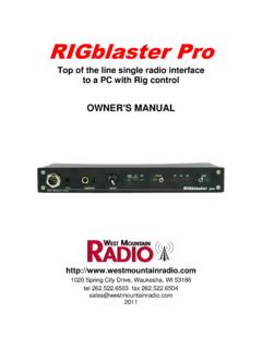
1 RIGblaster plus USBrig to sound card interfaceOWNERS MANUAL5TH EDITION Spring City Drive, Waukesha, WI 53186 tel fax MOUNTAINWEST MOUNTAINRADIORADIO 2008 West Mountain Radio , All rights trademarks are the property of their respective s Manual Contents of Package1- RIGblaster plus (NOTE: COVER IS LOOSE SO YOU MAY EASILY REMOVE IT TO INSTALL JUMPERS)1- Accessory Zip Lock bag. Contents: 4 - Black cover screws #6 sheet metal 8 - Single pin jumper wires 5 - 2 pin jumpers (shunts) blue, 4 - Adhesive pads 4 - Stick on protective feet1 - RIGblaster & RIGtalk CD1 - Microphone Cable (RJ45 to 8 pin screw on)2 - 1/8 stereo mini plug cables1 - DB9M to DB9F serial cable1 - USB to DB9 M serial adaptor (read instructions before plugging in)1 - 12 Volt wall cube power supply1 - Owner s manualMISC-Other cables or accessories that you ordered, see your invoiceIF YOU CAN T FIND IT HERE GO TO OUR SUPPORT PAGE.
2 Plus1 Owner s Manual RIGblaster plus USB Radio to sound card interfaceSTEP by STEP INSTALLATION INSTRUCTIONST hank you for purchasing a RIGblaster plus . We hope that it provides many hours of amateur Radio MAXIMUM ENJOYMENT PLEASE PROCEED IN ORDER, STEP BY STEP! DO NOT CONTINUE TO THE NEXT STEP UNTIL YOU HAVE CORRECTLY COMPLETED THE STEP YOU ARE ON. NOTE: IF YOU CALL FOR SUPPORT WE WILL TO NEED TO KNOW WHAT STEP OF THIS MANUAL YOU ARE HAVING A PROBLEM WITH. WE MAY NOT BE ABLE TO HELP YOU IF YOU HAVE NOT READ AND FOLLOWED THE FOLLOWING STEP BY STEP INSTALL SOFTWARE AND START RECEIVING: You do not need the RIGblaster for receive, only for transmit, so leave it in the box.
3 Put our CD in your CD drive and, after a few seconds, our CD menu should appear on your screen. If the menu does not appear, you probably need to set your CD ROM drive to autorun (as explained in Windows help). If you cannot get the CD to autorun, browse to the CDROM and double click the file in order to display our CD read the CD read me file first! We put it there for you to read! Note that this product manual is also on the CD but either the paper or electronic version may be more up to date with the latest version appearing on our support reading the Readme file, click the software collection XMIT button; click and select the PSK31 mode button, and then click the WINPSK program install button.
4 This installs a simple and easy PSK31 program to get started with. (Only if you are an advanced user should you install your choice of program or mode.)For more information on using and operating a sound card in a ham station read K1 UHF s The In s and Out s of a Sound Card in the October 2003 QST: your Radio s speaker output to your computer s line input (mic. on a laptop) using one of the supplied 1/8 stereo mini plug audio cables. Other connections may be used but we suggest you test initially with this simple hookup. If you have purchased a fixed level audio cable from us, made for your model Radio , then follow the instructions that came with that cable for connecting a receive audio signal.
5 Note that with the appropriate cable you may use any audio output on your Radio (speaker, headphone, record, phone patch, data audio out) and either of your computer s inputs, line or mic. inputs. To choose the best connection, consider the signal levels and your preference for operating convenience. WARNING: Be certain your computer is powered from the same AC house wiring circuit (on the same circuit breaker) as the rest of your ham station! This is safer and better for many reasons that are both related and unrelated to the RIGblaster plus2 Next tune in a signal for the mode and program you have installed and are running.
6 For PSK31 it is best to tune to USB. Open the sound card Recording Control panel and select whichever input you are using, mic. or line. Slide the slider up until see the recieve signals on the software s waterfall display. Note that on most computers you cannot set the input level to a sound program with the volume control sliders; you must use the recording control sliders! Set the level as described in the help files and instructions supplied with the program you are using. We do not write any software so our instructions are specifically for setting up a RIGblaster .
7 The software instructions should come with the confirming that your software is receiving properly, check that it will generate a transmit tone. You should be able to hear transmit tones, as sound, coming out of your computer when the software is placed in transmit mode. This is an important test of the computer and software operation. With no transmit sound you will not be able to transmit!If you have a problem with this step simply install and try another similar ham Radio program instead. If another program works you can be sure you there was a problem with the first program.
8 If several programs do not work then double check your soundcard virtual settings and your audio more information on using and operating a sound card in a ham station read K1 UHF s The In s and Out s of a Sound Card in the October 2003 QST: to the next step only after you have confirmed that you can receive signals and can hear transmit tones SET THE RIGblaster MICROPHONE WIRING JUMPERS: Different brands of radios use standard microphone connectors but wire them differently. We have solved this problem by using jumpers.
9 You must install jumpers to match your Radio s microphone wiring. The correct jumper configuration depends on the brand of Radio and the type of microphone connector. Metal eight pin round screw on microphone connector diagrams on page 12 and square RJ45 modular 8 wire telephone style plugs on page 13. Be certain to use the diagram that matches both your brand of Radio and the type of microphone connector that it you cannot find the appropriate jumper diagram for your Radio check our support page: : It is possible to damage your Radio by shorting out a DC voltage that may be on your mic.
10 Jack. Be certain you have the correct jumper wiring before turning on your s Manual TIP: The diagrams depict the actual appearance of the jumper block in the RIGblaster . The black squares with the wires depict where the black and white wire jumpers go. A black rectange denotes where a blue shunt jumper goes. A circle denotes that no jumper is installed on that completing the jumper Installation you may put the cover on. Carefully align the cover, making sure that the side screw holes line up.