Transcription of Variable Frequency Drives for a Vacuum Pump …
1 First published in Pumps and Systems Magazine, January 1998 Variable FrequencyDrives for a Vacuum Pump SystemBy Kevin Skelton, Graham Corporation_____Editor s Note: Responding to requests fromreaders many of whom work with vacuumpumping systems Pumps and Systems isintroducing this new column with theJanuary issue. Look for it periodically. In many process plant applications, usinga Variable Frequency drive (VFD) tocontrol the capacity of a liquid ringvacuum pump (LRVP) is an system designs consisted ofsizing the LRVP to operate efficiently for acertain portion of the process cycle andthen using a recycle control valve systemto maintain the desired LRVP suctionpressure.
2 This usually meant a loss ofsystem efficiency for most of theoperation liquid ring pump can be used in vesselevacuation or batch processes where theload volume is high at startup anddiminishes as the vessel is emptied andthe subsequent Vacuum level the end of the cycle the usual intent isto hold as high a Vacuum level as possiblefor a given period of time. This highvacuum level is a function of theproperties of the service liquid, whichboils or vaporizes as specific conditionsexist.
3 The liquid ring pump handles theleast amount of net capacity at this highvacuum. The majority of the capacity atthis point is the vaporized service LRVP operating at full load rpm isoversized for the Vacuum end point. Byslowing down the pump, the operator canmaintain the desired Vacuum , but pumpingcapacity is decreased, lowering the additional feature is that the drivecould be set up to operate at a speed thatstays within the horsepower rating of themotor and automatically adjusts as theLRVP power demand given frame size pump has apredetermined impeller tip speed rangethat would be programmed intooperational parameters in the controlroom.
4 The impeller tip speed is a functionof the impeller diameter. (The tip speed ortangential velocity is the rate of the outertip of the impeller.) The pump would thenrun in this tip speed range while stayingbelow the maximum horsepower rating ofthe motor. At the holding point, the pumpis slowed to the minimum speed lowenough to hold the desired Vacuum . Thissaves power and wear on the system design usually includes aprovision for over-capacity at the holdingpoint.
5 The device may be a Vacuum reliefvalve or recycle valve system. This designapproach can waste energy. An energyaudit of a particular facility may berequired to determine the feasibility ofinstalling VFD s on the current LRVP system. The system design engineersshould take a serious look at incorporatingthis approach in future LRVP Calculations ( ):rpm1/rpm2 = (hp1/hp2)2 Capacity1 / Capacity2 = rpm1/rpm2As an example, the capacity of a 25horsepower LRVP can be adjusted whileoperating from about 1000 rpm up to1750 rpm.
6 This represents an impeller tipspeed range of 40 to 70 ft/sec. At1750 rpm and at atmospheric suctionpressure, the capacity of this pump isapproximately 300 Actual Cubic Feet perMinute (ACFM). Depending on userspecific conditions, the brake horsepower(BHP) may exceed 25 briefly during anevacuation motor rpm can be reduced to keep thebrake horsepower below 25 during thisperiod. When the system is totallyevacuated and the Vacuum level is at itsmaximum, the pump is then slowed to aspeed at which it operates adequately anddoes not cavitate.
7 A word of caution -there is a minimum impeller tip speedwhich is a function of the pump scompression ratio or Vacuum level. If thepump speed is reduced below thisminimum impeller speed, the liquid ring willcollapse, causing system instability or upset. The minimum impeller speed can bedetermined to be thenoncondensable load quantity(which sets the pump suctionpressure) as a function of thecompression ratio desired.
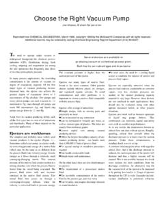
8 Moreenergy is required in the liquidring to achieve a high Vacuum thana low Vacuum , so as thecompression ratio increases, thepump must rotate faster than itdoes at lower compression the other hand, at low vacuumlevels it is beneficial to maintain ashigh an impeller speed as possiblein order to maximize the pump sACFM 1 illustrates a typical 50horsepower LRVP operating at ahigh Vacuum level. As you can see,the horsepower requirement dropsdramatically as the rpm of thepump is reduced while the suctionpressure remains illustrate the energy savingsover a year, the assumption wasmade that the pump was operatingcontinuously but at the holdingvacuum level only for 60% of Figure 1:Operating hp @ 1750 rpm =46 hpOperating hp @ 900 rpm =13 hp hp saved 33 hp33HP(.)
9 746 kW / lHP)(8760 hours /year)($ / kW hour )( ) $7884 This is the savings for one 50 hp liquidring Vacuum pump for one generating facilities use muchlarger LRVP systems to maintainvacuum level on steam turbinecondensers. These pumps operate over90 percent of the time at the holdingvacuum level, utilizing a Vacuum reliefvalve to introduce air load to the LRVPin order to maintain a Vacuum whichis above the cavitation larger sized LRVP operating @720 rpm with an impeller tip speed ofabout 65 has a bhp of the pump down to 475 rpmwill result in a bhp of 36 a difference of46hp.
10 46HP (.746 kW/lhp) (8760hr/yr)($ hr)(.9) = $16,233 per yearfor each condenser Vacuum savings can quickly becalculated because the hp requirementis the square of the ratio of the speeddifference. This calculation is fairlyaccurate and a good rule of thumb method of determining powerrequirements. Traditionally, thecapacity of a LRVP has beendetermined as a direct ratio of thespeed difference. This method holdstrue until the pump is at or near theend point, or noload operating capacity doesn t change due to thereduction in the pump rpm at highvacuum levels.