Transcription of INSTALLING LIQUID-RING VACUUM PUMPS - …
1 INSTALLING LIQUID-RING VACUUM PUMPS . The first lesson for operating LIQUID-RING VACUUM PUMPS is INSTALLING them properly The LIQUID-RING VACUUM pump is a specific form of rotary positive-displacement pump utilizing liq- uid as the principal element in gas compression. The compression is performed by a ring of liquid formed as a result of the relative eccentricity between the pump's casing and a rotating multi- bladed impeller. The eccentricity results in near-complete filling, and then partial emptying, of each rotor chamber during every revolution. The filling and emptying actions create a piston action within each set of rotor or impeller blades.
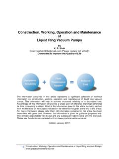
2 The pump's components are positioned in such a FIGURE 1 In the once through, no- manner as to admit gas when the rotor chamber is recovery system, the seat liquid emptying the liquid , and then allowing the gas to discharge is separated from the gas and discharge once compression is completed. Sealing allowed to flow into a drain areas between the inlet and discharge ports are provided, to close the rotor areas, and to separate the inlet and discharge flows. IN THE BEGINNING. SETTING UP. The proper installation of a LIQUID-RING VACUUM pump is critical to its subsequent operation and maintenance. The following LIQUID-RING VACUUM PUMPS are basically slow-speed, smooth-operat- installation guidelines are general recommendations that apply to ing rotating devices.
3 Nonetheless, it is important to ensure that the nearly all types of LIQUID-RING VACUUM PUMPS , but users should pump's frame or baseplate is mounted level and firmly anchored. refer to the specific recommendations of each manufacturer to ensure the best performance. PUMPS that are about 50 hp and above are best placed on a con- crete pad. Smaller units may be mounted on existing floors and As with any pump, care should be taken in unpacking the pump skids. All joints in piping, whether flanged or screwed, should be so as not to damage or misalign the assembly. For pump and free of strain and checked for leaks prior to start-up. motor units mounted on a baseplate, the unit should be lifted by the base only.
4 Slings or hooks should not be attached to the Normally, PUMPS that are supplied direct coupled to motors are pump or motor, since this can cause misalignment. Also, the aligned and test-run in the factory prior to shipment. However, pump should not be run until it is properly installed, nor should because of unforeseen forces and moments imposed on the pump it be run without a sealing liquid . during shipment and installation, it is necessary to check the cou- pling's alignment prior to startup. To do this correctly, the Normally, a pump's components are protected with a water-soluble guidelines of the coupling manufacturer should be followed as a preservative, which should be flushed from the unit if any fluid minimum, and exceeded where possible.
5 Other than water is utilized in a closed-loop system. PUMPS made of stainless steel or other non-ferrous materials may be shipped without preservative, that is, dry. Finally, the unit should be stored or installed such that any liquid present will not freeze. Chemical Engineering, November 1996 1. A means of stopping the flow when the pump is shut off A means of separating the gas- liquid exhaust mixture Once-through, no recovery. In this design, seal liquid is taken directly from a main and supplied to the pump (Figure 1). The liquid discharge is separated from the gas and wasted to a drain. No recirculation or recovery takes place. This is a common arrangement where conservation or contamination of the seal liquid is not a concern.
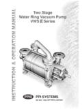
6 An automatic solenoid valve ensures the flow of the seal liquid in conjunction with the pump- motor's operation ( , when the motor stops running, the valve closes to prevent the casing FIGURE 2. In the partial-recovery sys- from filling with seal liquid ). With a manual tem, a part of the seal liquid is seal- liquid shut-off valve, care should be taken to recirculated back to the pump flash cautions to open the valve immediately before turning the motor on, and shutting the valve immediately before the motor is stopped. Partial recovery. Here, the seal liquid enters and For PUMPS utilizing V-belt drives, it is necessary to ensure that the leaves the pump in the same manner as with the once-through sheaves are properly installed and aligned before attempting to ten- arrangement (Figure 2).
7 After that, a portion of the seal liquid is sion the drive. The V-belts should be placed over the sheaves and recirculated from the separator tank to the pump, and the in the grooves without forcing them over the sides of the grooves. remainder is discharged from the separator and drained. When all belts are in their grooves, the centers are adjusted to take Fresh makeup seal liquid is introduced in sufficient quantity to up all slack and leave the belts fairly taut. When the pump is oper- maintain the proper temperature that is essential to good pump ating, the slack side should have a slight bow. After several days of performance. This type of arrangement is used where seal- liquid operation, re-tension the belts if necessary.
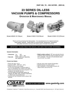
8 Slipping (squealing) at conservation is important (up to 50% reduction in fresh water startup are indications of insufficient tension. Excessive tension consumption is possible, and if other than water is utilized, the can shorten bearing life. If the unit is idle for an extended period consumption can be reduced more than 50%, depending upon of time, the tension on the belts should be removed. the fluid vapor pressure and temperature). Excessive heat (140 F and higher) should be avoided, since this Closed loop. This arrangement provides for total recirculation of over-cures the rubber and shortens belt life. The belts should the seal liquid .
9 A heat exchanger is added to the system to remove never be mixed or switched from one groove to another on the the heat of compression and condensation from the seal liquid sheaves, and should be replaced only with a matched set. Belt before it is reintroduced into the pump (Figure 3). For prolonged dressing should never be applied, and the sheaves should remain operation at high suction pressures, and when the system (heat free of oil and grease. exchanger, piping, valves, and so on) has excessive pressure drop losses, a circulating pump may be necessary. PIPING THE SEAL liquid With partial or total recovery arrangements, the seal- liquid level in the separator-recirculation tank should be at, or slightly below, The working principle of the LIQUID-RING pump is dependent the centerline of the pump shaft.
10 Provisions may also be made for upon a continuous supply of clean seal liquid (normally water, high-level overflow and low-level makeup on total recovery sys- but other suitable liquids can also be used). This liquid enters the tems. These level controls help prevent the starting of the pump pump through a connection on the casing and is discharged from with the casing full of water, since this could overload the motor the pump, along with the gas. and damage the pump. Three basic piping arrangements for the seal liquid can be used In fact, LIQUID-RING VACUUM PUMPS in any piping arrangement for VACUUM pump applications: once through, partial recovery, should not be started with a full casing of seal liquid .