Transcription of Understanding Process Vacuum Condensers - …
1 Understanding Process Vacuum CondensersProcess Vacuum Condensers are an integral part of a Vacuum systemSo often, a Process Vacuum condenser is considered stand-alone equipment, with little consideration given to how best to integrate it into a Vacuum system. Common practice has the Vacuum condenser specified as just another heat exchanger. There is a benefit toevaluating the condenser and Vacuum system as a complete unit. The benefits are reduced operating cost, less environmental impact,lower capital cost and improved product reclamation. Evaluate a Process Vacuum condenser and Vacuum system as a complete unit soan optimal engineering answer is Vacuum TechnologyWhere to BeginIt is most advantageous forparticular processes to use avacuum condenser ahead of avacuum system. A preliminaryassessment of the applicationis appropriate to determinevacuum condenser design.
2 Keyvariables to assess include:Pressure drop analysis should considerpressure drop between theprocess vessel and vacuumcondenser, pressure dropacross the condenser and pres-sure drop between the con-denser and Vacuum of the conden-sate. Does a single compo-nent condense? If there aremultiple condensables, arethe condensates immiscible,ideally miscible or nonideallymiscible?The amount of noncondensable gases. Noncondensable gases may come from theprocess itself or air leakage.\Do any of the components freeze at the colder temperatures?This is particularlycommon for applications in plastics, resins and plasticizer any of the components undergo exothermic or endothermic chemical reactions?For example, ammonia vapor and water react exothermically and that adds to the heatduty that must be rejected by a there reliable physical property, vapor pressure and vapor-liquid equilibriumdata available?
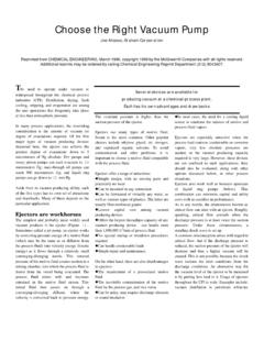
3 3An overview of terminology is impor-tant since definitions may vary fromone engineer to the next. Precondenser. A Vacuum condenserpositioned after a Process vessel,such as a still, evaporator or distilla-tion column, but before the vacuumsystem. In this issue, a precondenseris the Process Vacuum condenser. Intercondenser. A Vacuum condensersituated between two stages of vac-uum producing equipment, for exam-ple, two ejector stages. Vent condenser. A Vacuum condensersometimes placed behind a precon-denser. It uses a chilled cooling fluidto affect additional condensation andproduct recovery. Surface type condenser. A condenserwith a heat transfer surface that sep-arates vapors undergoing condensa-tion from a cooling fluid. Barometric condenser. A direct contactcondenser where vapors and coolingfluid are in contact with each other. Immiscible condensate.
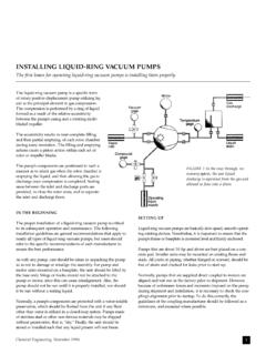
4 When multi-ple vapors condense and the con-densate formed does not mix, suchas oil and water. Miscible condensate. When multiplevapors condense and the condensatemixes, like water and ethylene fluidMotive fluidEjectorTerminologyTypical equipment layout showing Process vessel, precondenser and ejector system. Pressure DropPressure drop is a parasitic loss of unitefficiency. That is true for any system andis not a unique phenomenon of vacuumcondensers. However, the effect is moresignificant because of the Vacuum condi-tion. A 5 torr pressure drop is only per square inch (psi), however, at15 torr operating pressure it is a 33 per-cent loss in pressure. Pressure drop is animportant engineering constraint thatmust be drop reduces product recla-mation in the Vacuum condenser, increas-es the size and cost of the Vacuum system,adds to the utility use of the Vacuum sys-tem and causes the Vacuum condenser tobe larger.
5 A well-designed Process vacuumcondenser will not have pressure drop ofmore than 10 percent of the operatingpressure. Lower pressure drop is theresult of specialized designs for high- Vacuum applications. A high vacuumprocess condenser is not like an ordinaryheat exchanger. It has a markedly differenttube field layout and baffle BehaviorThe type of condensate formed affectscondenser design. Furthermore, the typeof condensate formed determines thetype of vapor-liquid equilibrium calcula-tions used. If condensates are miscible,whether ideally or nonideally, the con-densate should remain in intimate con-tact with the vapors so each is at thesame temperature. Common practice formiscible condensates is tubeside con-densing, since the vapors and condensateremain in contact with each other andare at the same condensing meets the pri-mary objective of contact and identicaltemperature but it is not always a practi-cal choice.
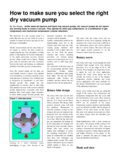
6 High- Vacuum applicationsresult in a massive volumetric flowrate,which cannot effectively be managedwith tubeside condensing. For example,50,000 pounds per hour (pph) of mixedhydrocarbon vapors (MW-80) at 15 torrand 300 F is 293,000 actual cubic feet perminute (ACFM). For in-tube condensingthe condenser size is a 100 x 72 AXLbecause so many tubes are required toensure reasonable vapor velocity. Whenshellside condensing is chosen, the bun-dle layout may be opened to increasecross-sectional flow area to maintainreasonable velocities. The comparableunit based on shellside condensing is a66 x 144 AXL, substantially smaller andless designs can accommodatemiscible condensates on the shellside,and for most applications, it is lessexpensive to condense high-volumetricflowrates GasVacuum condenser size and reclamationefficiency is greatly influenced by theamount of noncondensable gas.
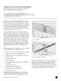
7 An accu-rate determination of noncondensablegas is critical. Erring on the conservativeside is recommended. The table shows theamount of noncondensable gas is directlyproportional to the amount of condensa-ble vapors not condensed. The greater Vacuum Condenser ConfigurationsShellside condensing X-shell designShellside condensing E-shell designnoncondensable gases, the greater theamount of condensable vapors that exitthe condenser with the noncondensable loading doubles, thereis twice the amount of condensablevapors that will not condense, assumingoperating pressure and temperature areconstant. Additionally, the amount ofnoncondensable gas changes the shape ofthe heat release curve. Greater amountsof noncondensable gas result in largervacuum Condensers and lower effectivelogarithmic mean temperature differ-ences (LMTDs).
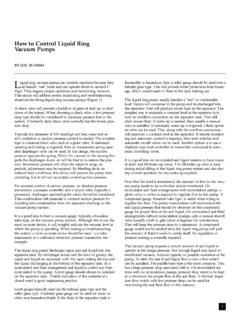
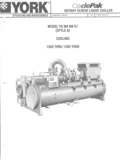
8 The graphs are an example of 100 torroperating pressure and 1500 pph of steamplus either 10 pph of air or 500 pph or cooling fluid enters at 85 F and exits at100 F. Process vapors are cooled to 100 or ReactionsIf the Process fluids undergo freezing orsome type of chemical reaction, it mustbe properly accounted for and are specialized designs for each ofthose particular applications. Equipment LayoutThe positioning of a Vacuum Process con-denser is important. There are designswhere the condenser is mounted directlyon top of the Process vessel to permitrefluxing of condensate into the processvessel or to eliminate piping pressuredrop altogether. If there is pipingbetween the Process vessel and vacuumcondenser, a hydraulic analysis of thepiping is necessary for the condenserdesign. The same is true for piping down-stream of the condenser.
9 It is alwayspreferable to install the condenser andfirst stage of the Vacuum equipment asclose to the Vacuum vessel as possible tominimize the costly impact of pressuredrop. Remember, a piping pressure dropof 2 torr at 10 torr operating pressure hasmore impact than a 10 torr piping loss at75 torr operating SoftwareThere is a lack of commercially availablesoftware available to accurately design orperformance check Process Vacuum con-densers when the operating pressure isbelow 40 torr. Almost invariably, thecommercial software will result in high-pressure drop and, consequently, poorreclamation efficiency. Therefore, prod-uct recovery suffers, the Vacuum systemcapital and operating costs appreciablyincrease, and less than optimal designsare for Predicting the Amount of Vapor Not Condensed[[Mj=((((((((SP VPi i=1nMncMWncVPjMWjMj=((((((((((((SP VPi ((xi i=1nMncMWncVPjxjMWj[[Mj=((((((((((((SP VPi ((xi i=1nMncMWncVPjxj((gj((gjMWjImmiscible condensateIdeally miscible condensateNonideally miscible condensateTerms: M = Mass flowrate, pphVP = Vapor pressure, torrMW = Molecular weight, lb/lb moleP = Pressure, torrx = Mole fraction in condensateg= Activity coefficientSubscript.))))))))))))))))))) )))))))))))))))))))))]]]]
10 J = Condensable component being evaluatednc = Noncondensable gasesi = All components that condense Heat Release Curve - Low NoncondensiblesTemperature - FHeat released - Btu/hr (thousands)1301201101009080 020040060080010001200140016001800 Heat Release Curve - High NoncondensiblesTemperature - FHeat released - Btu/hr (thousands)1301201101009080 0200400600800100012001400 LMTD = FTransfer rate = 135 Btu/hr ft2 FArea = 450 ft2 LMTD = FTransfer rate = 190 Btu/hr ft2 FArea = 240 ft2 Steam and airSteam and airCooling waterCooling waterComparison of low and high noncondensable unit design. Note the change in shape ofthe heat release curve and the effect that has on LMTD and exchanger specializing in this fieldhave proprietary software and special-ized engineering experience to developthe right answer for each unique applica-tion. Bundle design and tube layouts arevastly different from that normally usedfor typical shell and tube type is much to consider when a processvacuum condenser is required.