Transcription of DISCO Swing Check Valves CB PN 6 – PN 40, DN …
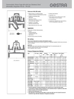
1 A Dd70 LMaterialsCB 24 S, CB 26, CB 26 A dn 50 300 mmCB 14, dn 50 200 mmCB 14, DN 250 300 mm60 da DLType Part designationNominal sizes EN referenceASTM1) DN equivalentCB 14 Body50 300 mm A 105 galvanizedgalvanizedFlap 50 300 mm NBR NBRCB 24 S Body 50 100 mm Bronze (CC 483K-GS) B 505 C 90 700125 300 mm Bronze (CC 332G) B 148 Alloy 952 Flap 50 300 mm Bronze (CC 332G) B 148 Alloy 952CB 26 Body 50 200 mm A 105250 300 mm A 105 Flap 50 150 mm A 351 CF 8 MC200 300 mm CB 26 A Body 50 250 mm AISI 316 TI300 mm A 351 CF 8 MCFlap 50 300 mm A 351 CF 8 MC1) Physical and chemical properties comply with EN DDISCO Swing Check Valves CBPN 6 PN 40, dn 50 DN 300 Short overall length to DIN EN 558-1, table 11, series , series 95-CB2 Application and FeaturesTypePNApplication for liquids, gases and vapoursFeaturesCB 14PN 16 particulaly suitable for water and compressed air rubber-elastic hinge, low weightCB 24 SPN 16 for salty fluids such as sea watercompact design, 2 bow springs, flap disc with stop for pipe protection, approved by Germanischer Lloyd, CB 24S also approved by Bureau VeritasCB 26PN 40 for industrial applicationsCB 26 APN 40 for low temperatures and aggressive fluidsWeights and Dimensions Nominal size Dimensions [mm] Weight [kg]
2 DN CB 14 CB 24 S, CB 26, CB 26 A CB14 CB 24 S CB 26 [mm] [in] D L a d7) D L a d7) CB 26 A 50 2 98 14 45 47 98 17 40 50 65 21/2 118 14 60 64 118 20 50 64 80 3 132 14 70 75 132 24 58 75 100 4 154 14 90 98 154 27 72 99 125 5 184 16 115 124 184 32 88 125 150 6 209 16 145 148 209 32 112 144 200 8 264 18 185 196 264 42 150 198 250 10 319 35 220 242 319 47 182
3 244 300 12 375 43 270 288 375 52 216 292 ) Minimum flange bore and inside pipe DesignsTyp Seat Springsmetal-to-metal NBR EPDM FPM PTFE6) without spring special spring ( 30 up to ( 40 up to ( 25 up to ( 25 up to 110 C)4)150 C)4)200 C)4)200 C)4)CB 14 X6) X CB 24S OXOO O CB 26 O XOOO CB 26A O XOOO 4) Observe pressure / temp. ratings of the equipment5) Cover FPM ring with PTFE 6) Flap made from NBR (Perbunan) Temp. range: 10 C up to 80 CX : standardO : optional : not availablePressure/Temperature RatingsTypeNominal sizes DNPNp / T / [bar] / [ C]CB 14 50 300PN 1616 / -10 / / 80CB 24 S 50 300PN 1616 / - / / 2502)CB 26 50 150PN 4040 / -10 / / 3502)200 300PN 4040 / -10 / / 300CB 26 A 50 300PN 4040 / -10 / / 4502)3)2) Max.
4 Pressure/temperature rating for CB without ) If the operating temperatures exceed 300 C intercrystalline corrosion may occur. Do not subject the equipment to operating temperatures higher than 300 C unless intercrystalline corrosion can be ruled Swing Check Valves CBPN 6 PN 40, dn 50 DN 300 Short overall length to DIN EN 558-1, table 11, series , series 95-CB2V W = V V W = Equivalent water volume flow in [l/s] or [m3/h] = Density of fluid (operating condition) in [kg/m3]V = Volume of fluid (operating condition) in [l/s] or [m3/h] Required minimum volume flow V W for equipment without spring installed in verticalpipes with upward flow. Required minimum volume flow V W for equipment with standard spring and volume flow CB 24 S, 26, 26 ADNM inimum volume flows [m3]for full openingwithout springwith springXXV5046665710128010202010018303012 5304048150607080200901501602501602202603 00200300360 Values refer to water at 20 C.
5 Pressure Drop Charts 1000 The curves given in the chart are valid for water at 20 C. To read the pressure drop for other fluids the equivalent water volume flowrate must be calculated and used in the graph V values indicated in the chart are applicable for spring-assisted Valves with horizontal flow and to Valves without spring installed in vertical pipes with upward ,0050,010,020,050,10,20,5[bar]1002003004 0060010006040302010643210,60,40,3[l/s]Dr uckverlust pVolumenstrom VwPressure drop pVolume flow Vw[psi]10,50,20,10,05257[m3/h]1001000400 0101002003004006001000200030004000600010 000604030201064[ ]CB 14CB 24 S, CB 26, CB 26 A506580100125150200250300DN0,0050,010,02 0,050,10,20,5[bar]1002003004006001000604 0302010643210,60,40,3[l/s]Druckverlust pVolumenstrom VwPressure drop pVolume flow Vw[psi]
6 10,50,20,10,05257[m3/h]10010004000101002 0030040060010002000300040006000100006040 30201064[ ]Differential pressures at zero volume PressuresType DN Opening pressures [mm] [mbar]Direction of flowXVY CB 14 50 150 8 0 1)200 300 15 0 Type DN Opening pressures [mm] [mbar]Direction of flowwithout with spring springXXVYCB 24 S 50 150 5 12 7200 300 8 15 7 CB 26/ 50 80 5 12 7 1)CB 26 A 100 150 11 18 7200 300 18 25 71) Valves should not be used for downward flow applicati-ons, since the spring will not close the valve flap. Required minimum volume flowV W for equipment installed in horizontal volume flow CB 14 DNMinimum volume flows [m3]for full openingXV5012106518178029281004241125555 1150140100200260190250460360300610500 Values refer to water at 20 drop pVolume flow V wPressure drop pVolume flow V w