Transcription of Future Technology Devices International Ltd - FTDI
1 Future Technology Devices International Ltd (FTDI) Unit 1, 2 Seaward Place, Centurion Business Park, Glasgow, G41 1HH, United Kingdom Tel.: +44 (0) 141 429 2777 Fax: + 44 (0) 141 429 2758 E-Mail (Support): Web: Neither the whole nor any part of the information contained in, or the product described in this manual, may be adapted or reproduced in any material or electronic form without the prior written consent of the copyright holder. This product and its documentation are supplied on an as-is basis and no warranty as to their suitability for any particular purpose is either made or implied. Future Technology Devices International Ltd will not accept any claim for damages howsoever arising as a result of use or failure of this product.
2 Your statutory rights are not affected. This product or any variant of it is not intended for use in any medical appliance, device or system in which the failure of the product might reasonably be expected to result in personal injury. This document provides preliminary information that may be subject to change without notice. No freedom to use patents or other intellectual property rights is implied by the publication of this document. Future Technology Devices International Ltd, Unit1, 2 Seaward Place, Centurion Business Park, Glasgow, G41 1HH, United Kingdom. Scotland Registered Number: SC136640 Copyright 2010 Future Technology Devices International Limited Future Technology Devices International Ltd USB-COM232-PLUS4 Datasheet Document Reference No.
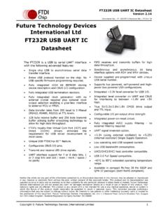
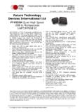
3 : FT_000148 Version Issue Date: 2010-04-12 Copyright 2010 Future Technology Devices International Limited 1 Document Reference No.: FT_000148 USB-COM232-PLUS4 Datasheet Version Clearance No.: FTDI# 97 1 Introduction Functional Description The USB-COM-Plus modules are a family of communication Devices . This model, USB-COM232-PLUS4, provides a simple method of adapting four legacy RS232 serial Devices to a modern USB port. This is accomplished by incorporating the industry standard FTDI FT4232H Hi-Speed serial bridge chip. The integrated electronics of the USB-COM232-PLUS4 utilise the FTDI FT4232H plus four RS232 level shifters and TXD/RXD LEDs to provide a visual indication of data traffic through the module.
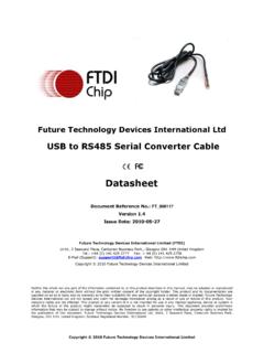
4 Figure USB-COM232-PLUS4 The module uses a standard USB-MINIB device connector for connection to an upstream host or hub port. RS232-level signals, including modem handshake signals, are available on an industry-standard DE-9P connector. The maximum RS232-level data rate is 1 Mbps. The USB-COM232-PLUS4 module requires USB device drivers, available free from , which are used to make the USB-COM232-PLUS4 appear as four Virtual COM Ports (VCP). This allows existing serial communications software, such as HyperTerminal, to exchange data through the USB-COM232-PLUS4 to a legacy RS232 peripheral device. LED Description The USB-COM232-PLUS4 uses nine LEDs to indicate a valid link as well as data traffic according to the following table: LED Colour Function Description quantity Yellow Enumerated ON when USB-COM-Plus is configured and ready 1 Green TxD Activity Flashes when data is transmitted from the USB-COM232-PLUS4 to the attached RS232 device 4 Red RxD Activity Flashes when data is transmitted from the attached RS232 device to the USB-COM232-PLUS4 4 Table LED Description Block Diagram Copyright 2010 Future Technology Devices International Limited 2 Document Reference No.
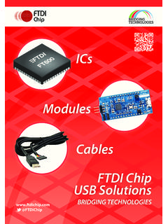
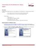
5 : FT_000148 USB-COM232-PLUS4 Datasheet Version Clearance No.: FTDI# 97 Figure USB-COM232-PLUS4 Block Diagram Block description USB MINI B Client Connector This connector provides the interface for connection to a USB Host or Hub port. The maximum cable length is 5 meters, according to the USB specification. FTDI FT4232H The FTDI FT4232H provides the Hi-Speed USB-to-Serial conversion. Operating system device drivers are required in order to work with the FT4232H to provide the quad Virtual COM Port serial interfaces. RS232 Level Shifter The RS232 level shifter converts the signals provided by the FT4232H into the voltage levels required by RS232 Devices . DE-9P Connector (Male) The DE-9P connector is configured in an industry standard (TIA/EIA-574) pin-out to provide connection to RS232 peripherals through standard cables.
6 See section USB MINIB Client Connector FTDI FT4232H USB Serial Bridge RS232 Level Shifter DE-9P Connector D DE-9P Connector B DE-9P Connector C DE-9P Connector A RS232 Level Shifter RS232 Level Shifter RS232 Level Shifter Copyright 2010 Future Technology Devices International Limited 3 Document Reference No.: FT_000148 USB-COM232-PLUS4 Datasheet Version Clearance No.: FTDI# 97 Features Adds four RS-232 serial ports by connecting to Hi-Speed USB interface. Easy plug & play installation and RS-232 device connection Provide Hi-Speed(480 Mbps) interface and works with USB & Host and Hub ports Industry Standard FTDI chip set & device drivers for maximum compatibility Microsoft Windows WHQL-certified, Mac OS X, Linux and Windows CE device drivers Installs as four standard Windows COM ports COM port number can be changed to any available COM port number, including COM1 to COM4, to support HyperTerminal, or any other serial communications software application running in Windows Supports Windows Server 2008, 2003, Vista, XP 2000, Linux, Mac OS X FIFO: 2K byte transmit buffer, 2K byte receive buffer RS-232 data signals.
7 TxD, RxD, RTS, CTS, DTR, DSR, DCD, RI, GND Powered by USB port. No external power adapter required. Serial port speed up to 1 Mbps Serial Communication Parameters o Parity: None, Even, Odd o Data bits: 7, 8 o Flow control: RTS/CTS , DTR/DSR, X-ON/X-OFF, None Four DE-9P male connectors LEDs indicate USB Enumeration, RxD, TxD for monitoring port status & easy diagnostics Operating temperature of -40 C to +85 C Performance Figures Parameter Performance USB Interface 480 Mbps USB Hi-Speed RS232 Interface Standard Windows baud rates (300bps to ) Custom baud rates (300bps to 1 Mbps) through baud rate aliasing. See FTDI Application Note: AN232B-05 Configuring FT232R, FT2232 and FT232BM Baud Rates Table - Performance Figures Part Number Description USB-COM232-PLUS4 Hi-Speed USB to 4-Port RS232 module Table - Ordering Information Copyright 2010 Future Technology Devices International Limited 4 Document Reference No.
8 : FT_000148 USB-COM232-PLUS4 Datasheet Version Clearance No.: FTDI# 97 1 Introduction .. 1 Functional Description .. 1 LED Description .. 1 Block Diagram .. 1 Block description .. 2 Features .. 3 Performance Figures .. 3 2 Installation .. 6 Example Applications and Configurations .. 6 Wiring .. 6 Device Driver Installation .. 7 Microsoft Windows .. 7 Mac OS X, Linux, Windows CE .. 10 3 Connections .. 11 External Connectors .. 11 USB .. 11 RS232 .. 11 4 Electrical details .. 12 USB .. 12 RS232 .. 12 5 Mechanical Details .. 13 Module Mechanical Dimensions .. 13 6 Physical Environment Details .. 14 Storage .. 14 Operating .. 14 7 Environmental Approvals & Declarations.
9 15 EMI Compatibility .. 15 15 Environmental .. 15 Reliability .. 15 MTTF .. 15 Import / Export Information .. 16 8 Troubleshooting .. 17 Hardware .. 17 Device Driver .. 17 Technical Support .. 18 9 Contact Information .. 19 Copyright 2010 Future Technology Devices International Limited 5 Document Reference No.: FT_000148 USB-COM232-PLUS4 Datasheet Version Clearance No.: FTDI# 97 10 Appendix A - List of Figures and 21 Appendix B - Revision History .. 22 Copyright 2010 Future Technology Devices International Limited 6 Document Reference No.: FT_000148 USB-COM232-PLUS4 Datasheet Version Clearance No.: FTDI# 97 2 Installation Example Applications and Configurations Wiring Insert the A-plug into an available USB Host or Hub port.
10 Insert the miniB-plug into the miniB-receptacle on the USB-COM232-PLUS4. RS232 cables have followed a standard 9-pin configuration on a D-sub connector since the mid 1980s. The USB-COM232-PLUS4 follows this standard as a Data Terminal Equipment (DTE) device. If the RS232 equipment being connected is a Data Communication Equipment (DCE) device, it s typical that a straight-through cable can be used. DTE Pin Number Signal Name DCE Pin Number 1 DCD = Data Carrier Detect 1 2 RXD = Receive Data 2 3 TXD = Transmit Data 3 4 DTR = Data Terminal Ready 4 5 GND = RS232 signal ground 5 6 DSR = Data Set Ready 6 7 RTS = Request To Send 7 8 CTS = Clear To Send 8 9 RI Ring Indicator 9 Table RS232 DTE to DCE connection with straight-through cable If the USB-COM232-PLUS4 is connected to another DTE device, a serial null-modem cable is required.