Transcription of Gray Code Generator and Decoder - CK Electronic
1 Gray code Generator and Decoderby Carsten KristiansenNapier UniversityNovember 2004 Title page Author:Carsten Kristiansen. Napier No: 04007712. Assignment title:Design of a Gray code Generator and Decoder . Education: Electronic and Computer Engineering. Module: Electronic Systems SE32102. Place of education:Napier University Edinburgh10 Colinton RoadEdinburgh EH10 5DT Lecturer:Jay Hoy. Assignment period:27. October 2004 - 3. December AbstractThis report describes how an Gray code Generator and Decoder are designed and simulated. Thereport takes a beginning in an introduction to what Gray code is, and can be used for in a practicalmatter of speaking.
2 There is described the design and simulation process separately for the Graycode Generator and the Gray code to binary Decoder . This reaches a final and complete schematic aswell as a simulation. Contents1. Practical use of the Gray Assignment Block Gray code State transition State Next state Simulation Gray code to BCD State transition State Next state Complete Simulation Software code Generator and decoderCarsten Kristiansen Napier No.: 040077122. IntroductionIn today's digital electronics, there are many different types of codes. The most used codecombination are known as the binary code , which is a code where every bit represents an integervalue.
3 There are however also codes where the combination and shifts between a 0 and a 1 thatis important like the Gray code . The Gray code are the type that's explained further in this report. Itwas used for the first time in a telegraph by the French engineer mile Baudot in 1878, but was notpatented before 1953, by the Bell Labs researcher Frank Gray, which also gave the name to thecode. The Gray code can best be described as a combination of binary numbers, with the advantagethat it only changes one bit at the time in the right sequence. It is possible to make the Gray code upto 4 bits of a maximum, cause more is not a unique sequence.
4 Below in figure 1 it is shown visualhow a 4 bit Gray code looks like. Fig. 1: 4 bit Gray codeThe letters A to D represents the 4 bits, where D is the Least Significant Bit (LSB), and A is theMost Significant Bit (MSB). The 4 bit Gray code starts from the position 0 and ends at position of the dark circles indicates a logical high ( 1 ), where all the empty boxes indicates a logicalzero ( 0 ). Note that with each shifts in position there are only increased or decreased with one(high) logical level. 6 Napier UniversityPosition0123456789101112131415 DCBAC arsten Kristiansen Napier No.: 04007712 Gray code Generator and Practical use of the Gray codeGray codes are mostly used where a mechanical position needs to be converted to a digital can be very convenient to use with cogwheels, to determine whether it is at the right position ornot.
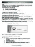
5 For instance, a production machine are running, and there would be cogwheels inside, whereone of them has a Gray code scale (shown below in figure 2) mounted, to be read by photo-sensorsand some electronics to decode the signals. Now if the cogwheel had to be very precise adjusted inits position, and at some time it would break a cog, so that the machine wouldn't run as desired (theprecision of the wheel would be wrong), it would then be possible for some Electronic to read fromthe Gray code scale , that the sequence of the code would be wrong, set of an alarm and stop themachine immediately. The figure 2 also shows the difference between the Gray code and the binary code , if they whereboth to be used on a cogwheel.
6 The dark part in the circle are the logical high, and the light are thelogical low levels. Again it would not be preferable not to use the binary code , because of the manyshifts there would be in the logical levels compared to the Gray University7 Fig. 2: Gray code vs. binary codeGray code Generator and decoderCarsten Kristiansen Napier No.: 040077123. Assignment specifications Use JK flip-flops and suitable logic gates to design a 4-bit binary Gray code Generator . Use the output of the Gray code Generator as inputs to a combinational logic circuit todecode the Gray code to produce the normal binary counting sequence.
7 Use TINA or any other simulation package to produce results to verify the Block diagramFrom the specifications a general block diagram can be presented. The block diagram below infigure 3 indicates what the desired options for the assignment 3: Gray code Generator and Decoder block diagramFor the Gray code Generator , a clock source is needed. This clock source should generate squarepulses at 1 Mhz. The Gray code Generator should then be able to send a 4 bit code parallel to theGray code Decoder , where the Decoder will convert the Gray code to a 4 bit binary code , which canbe used as an output to a table below indicates the conversion between the Gray code to the binary output.
8 The timesequence for each of the steps are also shown in codeBinary outABCD00-10000000011-20001000122-300110 01033-40010001144-50110010055-6011101016 6-70101011077-80100011188-91100100099-10 110110011010-11111110101111-121110101112 12-13101011001313-14101111011414-1510011 1101515-1610001111 Time [ S]QAQBQCQD8 Napier UniversityGray code GeneratorGray code Decoder1 MHz Clock sourceDisplayCarsten Kristiansen Napier No.: 04007712 Gray code Generator and decoder4. Gray code generatorTo design the Gray code Generator , it is analysed what is needed from the input to the output. Bylooking at the truth table for the Gray code , it is possible to follow the design procedure, and startwith a state transition diagram that shows which steps the Generator needs to fulfil.
9 To get thegenerator running there is a synchronous clock pulse between each State transition diagramThe state transition diagram in figure 4 indicates that there are 4 bits, and 16 steps that needs to bemapped. For this, 4 JK flip-flops are used, one for each bit. A table for the states of this type of flip-flop are shown below. The x's indicates a don't care University9 Fig. 4: Gray code state transition diagram000000110411008101012011150101611 1110111011001120001110011410111310001500 1030100711019 CLKCLKCLKCLKCLKCLKCLKCLKCLKCLKCLKCLKCLKC LKCLKCLKJK Flip-FlopJK0 00X0 11XX1X0Q Q+1 01 1 Gray code Generator and decoderCarsten Kristiansen Napier No.
10 : State tableA state table can then be made, where it is possible to derive the change state for each of the JK flip-flops. This is done by filling out the next state logic for the Gray code . Next state logicFrom the change state of the state table, the next state logic can be derived and written intoKarnaugh maps. The method used for this, is to draw a map for each output. To illustrate betterwhat is needed on the input to get the required output, the logic gates and connections for each ofthe reduced expressions are also shown to the right of each Karnaugh maps. 0 00 11 11 00 001XX0 100XX1 100XX1 000 XXQA QBQC QDJA change stateJA=QB QC QDFig.