Transcription of Proper Piping for Vacuum Systems - Graham …
1 Proper Piping for Vacuum SystemsLOREN WETZELGRAHAM MANUFACTURING designed Piping upstream and downstream of vacu-um equipment increases equipment efficiency and reducesmaintenance. It also minimizes Vacuum loss and pressure drop, takesadvantage of suction lift to enhance energy efficiency and decreasesthe risks of flooding equipment or shutting down , however, contractors or engineering firms doingplant layout frequently either route Piping to accommodate exist-ing process equipment, or try to fit pipes into available slipshod Piping configuration contributes greatly to plantdowntime and process addition, many plant startups and modifications are delayedbecause a simple Piping installation had been performed improp-erly.
2 And, if a problem is found after startup, it may not berectifiable without considerable trouble and expense. This articlediscusses the principles of Proper Piping design for common plantequipment, such as tailpipes, hotwells and float bubbles in tailpipes. A common hazard in barometric orshell-and-tube condenser tailpipes is accumulating from a shell-and-tube condenser, or cooling waterplus condensed steam or hydrocarbons from adirect-contact barometric condenser, always con-tain air or other non-condensible horizontal or slightly downward-sloped line isvulnerable to these gases, which cling to upper pipesurfaces.
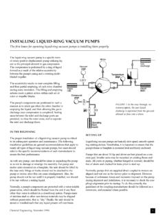
3 All types of pipe contain a certain amountof internal roughness and, because of this, gasestend to start clinging and building up in the small-est crevice. In addition, every flanged joint has aslight crack where a gasket is located, thus permit-ting another place for gases to these gases accumulate, they form tiny bubbles,growing into larger ones that eventually becomebig enough to partially or completely block offpiping at that point. The condensate cannot flowdownwards and soon its level rises, flooding has proven that if Piping changes direc-tion, it must form at least a 45-deg angle from thehorizontal (Figure 1).
4 With this amount of sloping,gases will either slide back up the pipe or continuedownward with the thrust of the flow-ing water. Observe that this is truewhether the condenser is a barometricor shell-and-tube a change in direction is required,there must always be a vertical straightdistance of five pipe diameters or four ftminimum between each change. Thisallows flowing liquid to develop a mini-mum velocity head and a straightdownward pattern before the first change in direction. There areno valves in the tailpipes shown (Figure 1), for two reasons: If a valve is accidentally left closed during startup or on turn-around, or if vibration closes a valve partly or completely, thecondition can flood condensers, cause Vacuum loss and shutdown operationChemical Engineering, November 19961 Figure 1 (top).
5 If Piping must change direction, it should form at least a 45-deg anglefrom the horizontal plane; the horizontal Piping in the rightmost drawing is vulnerableto gas accumulation. Any valve, by definition, causes pressure drop. Unlike asmooth piece of pipe, a valve creates a node, in which prod-ucts such as hydrocarbons, salts or rust can accumulate. Thisleads to excessive pressure drop, or can result in closing offpiping completely and possibly shutting down operationsCONFIGURING FOR SUCTION LIFTS uction lift is a function of Vacuum Systems that can be used toadvantage in Piping (Figure 2).
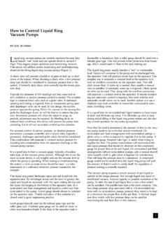
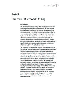
6 For example, it can enhance apumping system by reducing the load on an existing , for instance, pumping a liquid from one level up 80 ftto a vessel operating under Vacuum . The Vacuum or suction liftcan be used to reduce the total dynamic head (TDH) require-ments for the system s pump and reduces the horsepower used and possibly the motor size,thus saving energy and money. Another application is to merelymove liquid from one tank to another without a find a specific value for a given piece of equipment with Figure 2,use the lowest expected condenser pressure at the minimum cooling-water temperature at the inlet (for barometric Systems ), or theminimum condensing pressure due to loading.
7 The barometric pres-sure, in addition to the absolute pressure in the condenser, greatlyaffects the suction lift. I recommend using the highest recorded baro-metric pressure for calculation, and taking 80% of the theoreticalsuction lift to cover any overlooked an actual check of suction lift, obtain the barometric pressuredirectly at the installation point, and measure the condenser orvessel absolute pressure. Using Figure 2, move vertically upwardfrom the actual condenser pressure reading, to the barometricpressure. At the intersection, move horizontally to the left to readsuction lift in ft HEIGHTSR ecommended minimum effective tailpipe heights are shown,based on water at 32 F (Table, opposite page).
8 This height shouldbe based on the absolute maximum recorded barometric pressurefor given equipment, regardless of the anticipated condenser oper-ating pressure. This pressure information must be used in pipingdesign when Vacuum equipment is placed in a building or an ele-vated example, consider an installation site with a highest recordedbarometric pressure of 30 in. Hg. The plant has been laid out,and the most-economical placement of the Vacuum vessel (assumea process precondenser) is at an elevation of 32 ft, next to theevaporator. Based on the maximum pressure, the mini-mum effective tailpipe for water should be 34 result, however, is that water will flood the pre-condenser by2 ft.
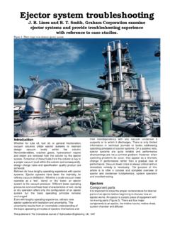
9 As something must be changed, the logical solution is tomove the evaporator and condenser to the next floor level, or toelevate them enough to overcome the that the values in this chart are based on water; heightsshould be corrected if any hydrocarbons or other substances arepresent. For hydrocarbons, good installation practice is to use atleast 45 ft, regardless of barometric is difficult to predict actual heights needed for hydrocarbonsunder Vacuum . Some have a tendency to foam, which suggeststhe rule-of-thumb minimum of 45 feet. If the specific gravity ofthe liquid in the tailpipe is known, the height should be DESIGNThe designer mustcarefully consider openhotwell design in aprocess (Figure 3).
10 Good practice recom-mends that the hotwellarea be equal to the tailpipe volumemeasured from the bot-tom of the tailpipe to thepoint of overflow (not less than 12 in.). The large volume is need-ed to ensure there is enough liquid present to seal the Vacuum is produced, the water rises in the tailpipe to theheight induced by the Vacuum , minus the barometric pressure. Ifthere is insufficient hotwell area present, the seal will be brokenand air drawn into the tailpipe, affecting the performance of vac-uum-producing equipment and the process. The pressure couldrise dramatically, affecting the process pressure, and possibly shut-ting down plant Engineering, November 19962 Figure 2.