Transcription of Differential Impedance - UltraCAD
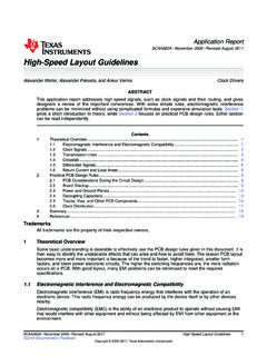
1 This article appeared in Printed Circuit Design, a Miller Freeman publication, August, 1998 1998 Miller Freeman, Inc. 1998 UltraCAD Design, when you thought you had mastered Zo, the charac-teristic Impedance of a PCB trace, along comes a data sheetthat tells you to design for a specific Differential to make things tougher, it says things like: .. since thecoupling of two traces can lower the effective Impedance , use50 Ohm design rules to achieve a Differential Impedance ofapproximately 80 Ohms! Is that confusing or what!!This article shows you what Differential Impedance more than that, it discusses why it is, and shows you howto make the correct Trace:Figure 1(a) illustrates a typical, individual trace.
2 It has acharacteristic Impedance , Zo, and carries a current, i. Thevoltage along it, at any point, is (from Ohm s law) V = Zo* case, trace pair:Figure 1(b) illustrates a pair of traces. Trace 1 has acharacteristic Impedance Z11, which corresponds to Zo,above, and current i1. Trace 2 is similarly defined. As webring Trace 2 closer to Trace 1, current from Trace 2 beginsto couple into Trace 1 with a proportionality constant, , Trace 1 s current, i1, begins to couple into Trace 2with the same proportionality constant. The voltage on eachtrace, at any point, again from Ohm s law, is:V1 = Z11 * i1 + Z11 * k * i2 Eqs. 1V2 = Z22 * i2 + Z22 * k * i1 Now let s define Z12 = k*Z11 and Z21 = k*Z22. Then,Eqs. 1 can be written as:V1 = Z11 * i1 + Z12 * i2 Eqs.
3 2V2 = Z21 * i1 + Z22 * i2 This is the familiar pair of simultaneous equations weoften see in texts. The equations can be generalized into anarbitrary number of traces, and they can be expressed in amatrix form that is familiar to many of case, Differential pair:Figure 1(c) illustrates a Differential pair of traces. Re-peating Equations 1:V1 = Z11 * i1 + Z11 * k * i2 Eqs. 1V2 = Z22 * i2 + Z22 * k * i1 Now, note that in a carefully designed and balanced situ-ation,Z11 = Z22 = Zo, andi2 = -i1 This leads (with a little manipulation) to:V1 = Zo * i1 * (1-k) Eqs. 3V2 = -Zo * i1 * (1-k)Note that V1 = -V2, which we already knew, of course,since this is a Differential (odd mode) Impedance :The voltage, V1, is referenced with respect to effective Impedance of Trace 1 (when taken alone this iscalled the odd mode Impedance in the case of differentialpairs, or single mode Impedance in general) is voltage di-vided by current, or:Zodd = V1/i1 = Zo*(1-k)And since (from above) Zo = Z11 and k = Z12/Z11, thiscan be rewritten as:Zodd = Z11 - Z12which is a form also seen in many proper termination of this trace, to prevent reflec-tions, is with a resister whose value is Zodd.
4 Similarly, theodd mode Impedance of Trace 2 turns out to be the same (inthis special case of a balanced Differential pair). Differential ImpedanceWhat s the Difference?Douglas BrooksRdiffZ11Z22 Zoi1i2iZ11Z22i1 + ki2i2 + ki11221(a)(b)(c)ki2ki1 Figure 1 Various Trace ConfigurationsDifferential Impedance :Assume for a moment that we have terminated bothtraces in a resister to ground. Since i1 = -i2, there would beno current at all through ground. Therefore, there is no realreason to connect the resisters to ground. In fact, some peo-ple would argue that you must not connect them to groundin order to isolate the Differential signal pair from groundnoise. So the normal connection would be as shown in Fig-ure 1(c), a single resister from Trace 1 to Trace 2.
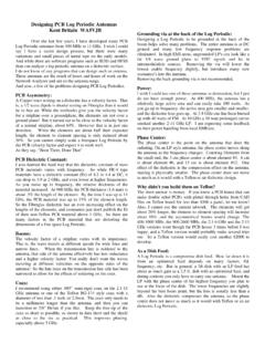
5 The valueof this resister would be the sum of the odd modeimpedance for Trace 1 and Trace 2, orZdiff = 2 * Zo * (1-k) or 2 * (Z11 - Z12)This is why you often see references to the fact that adifferential pair of traces can have a Differential impedanceof around 80 Ohms when each trace, individually, is a 50 Ohm :To say that Zdiff is 2*(Z11 - Z12) isn t very helpfulwhen the value of Z12 is unintuitive. But when we see thatZ12 is related to k, the coupling coefficient, things can be-come more clear. In fact, this coupling coefficient is thesame coupling coefficient I talked about in my Brookspeakcolumn on crosstalk (Footnote 1). National Semiconductorhas published formulas for Zdiff that have become acceptedby many (Footnote 2):Zdiff = 2*Zo[ *exp( *S/H)] (Microstrip)Zdiff = 2*Zo[ *exp( *S/H)] (Stripline)where the terms are as defined in Figure 2 and exp() means e, the base of the natural logarithm, raised to thepower in the parentheses.
6 Zo is as traditionally defined(Footnote 3).Common Mode Impedance :Just to round out the discussion, common modeimpedance differs only slightly from the above. The firstdifference is that i1 = i2 (without the minus sign.) Thus becomeV1 = Zo * i1 * (1+k) Eqs. 4V2 = Zo * i1 * (1+k)and V1 = V2, as expected. The individual trace Impedance ,therefore, is Zo*(1+k). In a common mode case, both traceterminating resisters are connected to ground, so the currentthrough ground is i1+i2 and the two resisters appear (to thedevice) in parallel. Therefore, the common mode impedanceis the parallel combination of these resisters, orZcommon = (1/2)*Zo*(1+k), orZcommon = (1/2)*(Z11 + Z12)Note, therefore, that the common mode Impedance is ap-proximately the Differential mode Impedance for tracepairs.
7 Microstrip StriplineFigure 2 Definition of terms for Differential Impedance calculationsFootnotes:1. Crosstalk, Part 2: How Loud Is It? Brookspeak, De-cember, See National Semiconductor s Introduction to LVDS (page 28-29) available from their web site their Transmission Line RAPIDESIGNER Operationand Applications Guide , Application Note See PCB Impedance Control, Formulas and Re-sources , Printed Circuit Design, March, 1998, p12. Theformulas are:Zo=87*Ln[ (.8W+T)]/SQR( r+ ) (Microstrip)Zo=60*Ln[ (H)/(.8W+T)]/SQR( r) (Stripline)hWSWWWS