Transcription of Ultra High Precision, Z-Foil Audio Resistor …
1 Ultra High Precision, Z-Foil Audio Resistor Minimizes Noise and Distortion in the Signal Path with TCR of ppm/ C, Tolerance to % and High Linearity or Low Voltage Coefficient of Resistance (VCR) of ppm/VVARV ishay Foil Resistors Document Number: 63140 For any questions, contact: 03-Jan-121 INTRODUCTIONMany manufacturers and users of precision electronic equipment suffer needlessly from unexplained instabilities and drifts due to noise effects. They resign themselves to making constant adjustments and troubleshooting. But in fact these can be avoided. Instability is often traceable to a few supposedly fixed resistors which are not really fixed at all. If these resistors would only retain their original values, there would be no need for costly controls and other compensating circuitry. That s why the only Resistor for applications such as these is Vishay Bulk Metal Foil.
2 In high-end Audio equipment, careful selection of resistors is one of the best ways to avoid or minimize noise and distortion in the signal path. Noise is an unwanted wide spectrum signal that may be superimposed on any useful signal, including DC. Resistors, like other passive components, are noise sources to various degrees, depending upon resistance value, temperature, applied voltage, and Resistor type. Many experiments have been done to show why some resistors are noisier than others. But the only test that Audio experts and audiophiles have agreed on is comparing the level of fidelity that results when different Resistor technologies are used in actual Audio analog Audio applications require low intrinsic noise, high linearity of amplification, and minimal dynamic distortion. The typical Audio amplifier consists of a voltage preamplifier (preamp) and power amplifier (final driver).
3 The voltage preamplifier deals with low-level signals. That is why its intrinsic noise level is critical. Resistors are among the principal noise sources in the amplifiers. The main requirements for the Audio power amplifier are high linearity of amplification and minimal dynamic distortion. Vishay Foil resistors are characterized by very low intrinsic non-linearity of the resistive element, which is made from cold-rolled bulk metal. The VAR, composed of Vishay s Bulk Metal Z-Foil technology, with improved sound quality, provides a combination of low noise and low inductance/capacitance, making it unrivalled for applications requiring low noise and distortion-free Temperature coefficient of resistance (TCR): ppm/ C typical (0 C to + 60 C,+ 25 C ref.) ppm/ C typical (0 C to + 125 C, + 25 C ref.) Rated power: to W at + 70 C Resistance tolerance: to % ( is available) Load life stability: to % at 70 C, 2000 h at rated power Resistance range: 10 to 100 k "Naked Z-Foil Resistor " design without molding or encapsulation adds an additional dimension for reducing signal distortion and increasing clarity in signal processing.
4 Vishay Foil resistors are not restricted to standard values; specific "as-required" values can be supplied at no extra cost or delivery ( 1K2345 vs 1K) Electrostatic discharge (ESD) at least to 25 000 V Non-inductive, non-capacitive design Rise time: 1 ns, effectively no ringing Current noise: V (RMS)/Volt of Applied Voltage (< - 40 dB) Thermal EMF: V/ C Voltage coefficient: < ppm/V Thermal stabilization time < 1 s (nominal value achieved within 10 ppm of steady state value) Inductance: < H typical The Z-Foil chip in the VAR has been especially treated to increase load life stability. Terminal Finish: lead (Pb)-free or tin/lead alloy(1) Prototype quantities available in just 5 working days or sooner. For more information, please contact better performances please contact Foil Resistors any questions, contact: Number: 631402 Revision: 03-Jan-12 While the regular foil resistors are already widely acknowledged as the leading resistors for Audio applications, the special naked Z-Foil Resistor design without mold or encapsulation, adds an additional dimension for reducing signal distortion and increasing clarity in signal processing.
5 Our application engineering department is available to advise and to make recommendations. For non-standard technical requirements and special applications, please contact Metal Foil resistors owe their low current noise and high linearity to the type of material they re made of: a several microns thick cold-rolled metal foil. Every real-world Resistor possesses certain nonlinearity of its electrical resistance (nonlinearity of volt-ampere characteristic). The degree of nonlinearity depends on two factors: Micro factors: internal microstructure of resistive material. Macro factors (laser trimming cuts cleanness, micro cracking in resistive element resulting from laser trimming, quality of contacts between resistive element and terminals, etc.).As for the microstructure, the most linear materials are pure metals and metal alloys in bulk, such as the foil in Bulk Metal Foil resistors.
6 When the same materials are deposited in the form of very Thin (nanometer range) Films, they are less linear. Even less linear are composite materials like resistive cermets in Thick-Film resistors or carbon compositions in carbon composition macro factors that cause nonlinearity in other types of resistors aren t relevant to foil resistors. Indeed, laser trimming of foil resistors consists of cutting shorting jumpers and does not damage current carrying portions of resistive element. Terminals in foil resistors are an integral part of the foil resistive element. This insures high-quality contact between resistive element and terminalsSeveral types of noise are found in resistors:Thermal noise is caused by thermal movement of electrons in resistive material and gets worse as resistance and temperature increase. Thermal noise can be reduced by reducing resistance, temperature, or signal or fluctuation noise is caused by the discrete nature of charge carriers and fluctuation of their number in the unit of volume.
7 Shot noise can be reduced by reducing bandwidth or increasing current. The spectral density of voltage in both thermal and shot noises is uniformly distributed in entire range of frequencies ( white noise). The level of these types of noise does not depend on Resistor type (resistive element material).Current (excess, flicker) noise has 1/f type spectral density of voltage ( pink noise). Its level essentially depends on Resistor material. Current noise can be reduced by a) avoiding use of the low frequency band, b) reducing current, c) increasing the volume of resistive material, by using resistors with higher rated power than is needed for proper power dissipation, or d) using less noisy resistive materials. Carbon composition resistors are the noisiest such device type followed by Thick Film and Thin Film resistors. The least noisy are bulk metals and metal alloys (foil, wire).
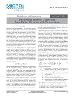
8 At that, negligible capacitance/inductance of foil resistors (when compared to wirewound resistors) significantly reduces probability of self-excitation or "ringing" of amplification is why Bulk Metal foil resistors are such a good choice for low-noise 1 - TYPICAL RESISTANCE / TEMPERATURE CURVE ( Z-Foil ) + 500+ 200+ 1000- 100- 200- 300- 500- 55- 25+ 25+ 60 + 75+ 100 + 125 Ambient Temperature ( C) RR(ppm) ppm/ C- ppm/ ppm/ ppm/ ppm/ C- ppm/ C- 400+ 300+ 400 TCR chord slopes for different temperature rangesTABLE 1 - RESISTANCE VERSUS TCR (- 55 C to + 125 C, + 25 C Ref.)(2)RESISTANCE VALUE( )TYPICAL TCR AND MAXIMUM SPREAD (ppm/ C)TIGHTEST TOLERANCE(%)100 to < 100K to < 100 to < 50 :(1) Pb containing terminations are not RoHS compliant, exemptions may apply(2) For non-standard requests, please contact application engineering at 2 - STANDARD DIMENSIONSLead Material #22 AWGR ound Solder Coated CopperWLLSHLLS oldered PCBThis product is fragileand may be damagedif assumes noresponsibility fordamage caused byimproper 2 - SPECIFICATIONSRESISTANCE RANGE ( )MAXIMUM WORKING VOLTAGEAMBIENT POWER RATINGDIMENSIONSat+ 70 Cat+ 125 CINCHESmm10 to WW: max.
9 L: max. H: max. LL: LS(1): : max. L: max. H: max. LL: LS: Foil Resistors Document Number: 63140 For any questions, contact: 03-Jan-123 Note1. An additional lead space option is available: " ( mm). For these specifications - please specify VARJ (see Table 3) when placing an 3 - POWER DERATING CURVE200 %175 %150 %125 %100 %75 %50 %25 %0- 75- 50- 250+ 25 + 50 + 75 + 100 + 125 + 150 + 175 + 200 Ambient Temperature ( C)Percent of Rated Power at + 125 C- 55 C+ 70 CDouble Rated PowerRated Power FIGURE 4 - TRIMMING TO VALUES (Conceptual Illustration)Mutual InductanceReduction dueto OpposingCurrent inAdjacent LinesCurrent PathBefore TrimmingNote: Foil shown in black, etched spaces in whiteInterloop CapacitanceReduction in SeriesTrimming ProcessRemoves this Materialfrom Shorting Strip AreaChanging Current Pathand IncreasingResistanceCurrent PathAfter TrimmingTo acquire a precision resistance value, the Bulk Metal Foil chip is trimmed by selectively removing built-in shorting bars.
10 To increase the resistance in known increments, marked areas are cut, producing progressively smaller increases in resistance. This method reduces the effect of hot spot and improves the long term stability of the hybrid 3 - GLOBAL PART NUMBER INFORMATION(1)NEW GLOBAL PART NUMBER: Y070680K5000T9L (preferred part number format)DENOTES PRECISIONRESISTORVALUEC haracteristicsYR = K = k 0 = standard part, tin/lead termination 9 = standard part, lead (Pb)-free termination 1 - 999 = customPRODUCT CODERESISTANCE TOLERANCEPACKAGING0706 = VAR 0707 = VARJT= % Q= % A= % B= % C= % D= % F= %L = bulk packFOR EXAMPLE: ABOVE GLOBAL ORDER Y0706 80K5000 T 9 L:TYPE: VAR VALUE: k ABSOLUTE TOLERANCE: % TERMINATION: lead (Pb)-free PACKAGING: bulk packHISTORICAL PART NUMBER: VAR T 80K5 T B (will continue to be used)VART80K5 TBMODELTERMINATIONRESISTANCE VALUETOLERANCEPACKAGINGVART = lead (Pb)-free None = tin/lead k T= % Q= % A= % B= % C= % D= % F= %B = bulk packVARV ishay Foil Resistors any questions, contact: Number: 631404 Revision: 03-Jan-12 Note(1) For non-standard requests, please contact application Precision Group, Disclaimer NoticeDocument No.