Transcription of IXYS P-channel MOFETs Applications
1 ixys P-channel Power MOSFETs and Applications Abdus Sattar, Kyoung-Wook Seok, IXAN0064 1 ixys Corporation, 1590 Buckeye Drive, Milpitas, CA 95035, Phone: 408-457-9000, October, 2008. Introduction: ixys P-channel Power MOSFETs retain all the features of comparable N- channel Power MOSFETs such as very fast switching, voltage control, ease of paralleling and excellent temperature stability. These are designed for Applications that require the convenience of reverse polarity operation. They have an n-type body region that provides lower resistivity in the body region and good avalanche characteristics because parasitic PNP transistor is less prone to turn-on [1].
2 In comparison with N- channel Power MOSFETs with similar design features, P-channel Power MOSFETs have better FBSOA (Forward Bias Safe Operating Area) and practically immune to Single Event Burnout phenomena [2]. Main advantage of P-channel Power MOSFETs is the simplified gate driving technique in high-side (HS) switch position [3]. The source voltage of P-channel device is stationary when the device operates as a HS switch. On the other hand, the source voltage of N- channel device used as HS switch varies between the low-side (LS) and the HS of the DC bus voltage.
3 So, to drive an N- channel device, an isolated gate driver or a pulse transformer must be used. The driver requires an additional power supply, while the transformer can sometimes produce incorrect operations. However, in many cases the LS gate driver can drive the P-channel HS switch with very simple level shifting circuit. Doing this simplifies the circuit and often reduces the overall cost. Main disadvantage of P-channel device is relatively high Rds(on) in comparison with that of N- channel device. This means the cost effective solutions with P-channel power MOSFETs require optimization of devices toward reduced Rds(on) [4].
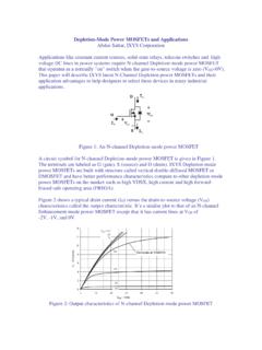
4 Figure 1: P-channel (left) and N- channel (right) MOSFET ixys Corporation has developed two families of P-channel Power MOSFETs covering VDS range of -50V to -600V and ID25 range of -10A to -170A. Details of the product selections are given in the appendix A. P-channel TrenchPTM Power MOSFETs in the range of -50V to -150V offer very low on-resistance, low gate charge, very fast switching and fast body diode. Planar PolarTM P-channel Power MOSFETs offer excellenet power performance in the range of -100V to -600V voltage.
5 Both families offer best in class performance in industry standard power packages and ixys propritary ISOPLUS family packages. ixys P-channel Power MOSFETs and Applications Abdus Sattar, Kyoung-Wook Seok, IXAN0064 2 ixys Corporation, 1590 Buckeye Drive, Milpitas, CA 95035, Phone: 408-457-9000, October, 2008. Gate driving for High-Side (HS) Switch: In this section, various gate driving techniques for half bridge circuit are presented. Driving P-channel MOSFET is much simpler and more cost effective than driving N- channel MOSFET as a HS switch [5]. LoadGateDrive ICGateDrive ICIn hIn lDzRzDhChRh1Rh2 DlRl1Rl2 MhMl Figure 2: P-channel gate driving example for PWM application Figure 2 shows one example of gate driving circuit for HS P-channel power MOSFET.
6 This is much simpler and more cost effective than the driving circuits in Figure 5 and 7 for N- channel MOSFET. In the circuit, Dz, Rz, and Ch were added to the typical gate driving circuit for an N- channel power MOSFET. The capacitor Ch , which holds DC voltage between the higher and lower gate drive circuits, must be much larger than the input capacitance of the P-channel MOSFET. Dz keeps the gate to source voltage in the range of Zener voltage to 0. The product of Ch and Rz determines the speed of the DC voltage adjustment across Ch.
7 If it s too small, there will be a large current, which can damage the gate drive IC or Dz. If it s too big, the P-channel MOSFET will switch on too slowly. This is due to the slower rise time of the gate pulse amplitude and can damage the MOSFET. Rh2 and Rl2 are resistors for controlling MOSFET turn off speed. (Rh1 + Rh2) and (Rl1 + Rl2) are resistors for controlling MOSFET turn on speed. In most cases, slower turn on speed than turn-off speed is desirable [4]. ixys P-channel Power MOSFETs and Applications Abdus Sattar, Kyoung-Wook Seok, IXAN0064 3 ixys Corporation, 1590 Buckeye Drive, Milpitas, CA 95035, Phone: 408-457-9000, October, 2008.
8 Figure 3: Single gate drive IC drives both P-channel and N- channel MOSFETs Figure 4: Dead times in single gate drive IC case In many cases, both P-channel and N- channel MOSFETs can be driven by a single gate drive IC as shown in Fig. 3. This is the most cost effective and simplest gate driving method of half-bridge. To avoid cross conduction, dead time is to be provided by the difference of turning on and turning off speed. If dead time is too short, there is a chance of too much heat generation and risk of MOSFET failure. If dead time is too long, the output voltage of the bridge circuit may be reduced.
9 With this circuit, at the beginning of turn on period of each MOSFET, the gate source voltage is not enough to fully turn on the MOSFET and it will make some additional power loss. So, this circuit may not be suitable for hard switching Applications . But, for some ZVS (Zero Voltage Switching) Applications , in which MOSFETs are turned on while opposite MOSFET operates in diode mode, this circuit can be cost effective [4]. ixys P-channel Power MOSFETs and Applications Abdus Sattar, Kyoung-Wook Seok, IXAN0064 4 ixys Corporation, 1590 Buckeye Drive, Milpitas, CA 95035, Phone: 408-457-9000, October, 2008.
10 Figure 5: N- channel MOSFET driving with pulse transformer Figure 5 shows an example of N- channel MOSFET driving circuit using a pulse transformer. The gate pulse height of this circuit is not sensitive to the duty ratio variation, unlike trivial pulse transformer driving circuit. Theoretically, there is no limitation in duty ratio. But, in the actual circuit, several parasitic components limit the usable duty range. At gate turn-off, the transistor Qh discharges the gate charge. Rb is the base resistor for Qh. The small capacitor Cb is used to accelerate the speed of Qh.