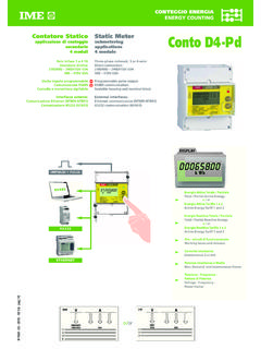
Transcription of SCHEMI D’INSERZIONE • WIRING DIAGRAMS Conto …
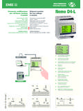
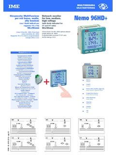
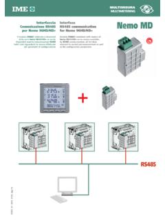
1 10782104W1 MDPMDT empo di mediaAverage timeTemps de moyenneMittlerezeitVelocit comunicazioneBaud rateVitesse de communication bertragungsdatengeschwindigkeitIndirizzo comunicazioneCommunication addressAdresse de communicationKommunikationsadressePotenz a attiva mediaActive power demandPuissance moyenne activeLeistungsmittelwertPicco potenza attiva mediaActive power max. demandVal. max. puissance moyenne activeMax. LeistungsmittelwerttIMEbAUdAddrCrCCRCCRC CRCCRC Glossario Glossary Glossaire W rterverzeichnisBit di parit Parity bitBit de parit Parit tsbitPArnonENessunaNoneAucunKeinPariEven PairGeradeDisparioddImpairUngeradeEVEnod dPLSt ACtPLSt rEAEnergia associata attivaAssociated energy active Energie associ e activeMessgr e WirkenergieEnergia associata reattivaAssociated energy reactiveEnergie associ e r activeMessgr e BlindenergiePeso impulsoPulse weightPoids impulsionImpulsgewichtDurata impulsoWidth of the pulseDur e d impulsionImpulsdauerPLSUPLSdXXXL1L2L3 NXXXLOADI N P U TO U T P U T RS 485 Rx / Tx GND + 1346793334 3511S 1000/365 SCHEMI D INSERZIONE WIRING DIAGRAMSSCHEMAS DE RACCORDEMENT
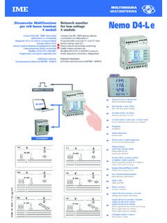
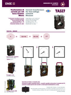
2 ANSCHLU BILDXXXL1L2L3 NXXXLOADI N P U TO U T P U T1346791115 29S 1000/373CE4 DMID32CE4 DMID31 Cod. CE4 DMID31 - CE4 DMID32 Conto D4-Pd MID 10782104 WVia Travaglia 720094 CORSICO (MI) ITALIATel. +39 02 ISTRUMENTI MISURE ELETTRICHE SpAI 04/161 Codice prodotto2 Classe di precisione3 Temperatura impiego4 Anno e settimana di fabbricazione5 LED metrologico6 Simbolo impulso7 Tastiera8 Ente certificatore9 Anno di apposizione10 Numero certificazione11 Uscita ( RS485)12 Inserzione su linea trifase 4 fili, 3 sistemi13 Frequenza14 Peso impulso LED metrologico15 Corrente16 Tensione17 Doppio isolamento18 Consultare il manuale d uso prima dell installazione19 Numero matricola1 Code du produit2 Classe de pr cision3 Temp rature de fonctionnement4 Ann e et semaine de fabrication5 LED m trologique6 Symbole impulsion7 Clavier8 Organisme de certification9 Ann e de apposition10 Num ro de certification11 Sortie (ex.)
3 Communication RS485)12 Branchement sue ligne triphas e 4 fils, 3 syst mes13 Fr quence14 Poids d impulsion du LED m trologique15 Courant16 Tension17 Double isolation18 Consulter la notice d utilisation avant de la mise en place19 Num ro de fabrication1 Product code 2 Accuracy class3 Working temperature4 Manufacturing year and week5 Metrological LED6 Pulse simbol7 Keyboard8 Certifying board9 Year of affixing10 Certifying number11 Output ( communication)12 Connection on 3-phase 4 wire, 3 system line13 Frequency14 Metering LED pulse weight15 Current16 Voltage17 Double insulation18 Consult the instruction manual before mounting19 Serial number1 Produktscode2 Genauigkeitsklasse3 Betriebstemperatur4 Herstellungsjahr und -Woche5 Metroligische Led6 Pulszeichne7 Tastatur8 Zertifizierungsstelle9 Anlegungsjahr10 Zertifizierungsnummer11 Ausgang ( RS485-Kommunication)12 Drehstromleitung 4 Leiter, 3 Systeme-Anschluss13 Frequenz14 Impulsgewicht der metrologischen Led15 Strom16 Spannung17 Doppelisolierung18 Bitte lesen das Handbuch bevor den Einbau19 HerstellungsnummerFRONT FRAMEFACE AVANTFRONTTEILFRONTALE 2654280001 42 2013CE4 DMID31 -25 C33 xx 230/400V230/400V0,5-10(63)A0,5-10(63)
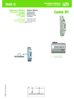
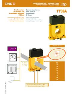
4 A 5500 -- 60Hz60 HzMetering LED 1Wh/impMetering LED 1Wh/imp RS485 communication RS485 communicationM140120T1036832167854109121 61718151913141110782104W210782104W3 MOUNTING INSTRUCTIONSM ounting of this equipment must be carried out just by skilled personnel. Before mounting, please make sure that the data on the label (measuring voltage, measu-ring current, frequency)correspond to the network on which the meter must be meter is designed for connection on 3-phase, 4 wire the WIRING scrupulously respect the WIRING diagram; an error in connection unavoidably leads to wrong measurements or damages to the equipment doesn t need any case of damage to the equipment or malfunctioning, please contact the manufactu-rer. No-one is entitled to carry out repairs on the meter; any tampering will lead to for-feiture of the guarantee as well as the validity of the certification.
5 EU DECLARATION OF CONFORMITYThis equipment meets the 2014/32/EU, 2014/30/EUand 2014/35/EU European Stan-dards. The EU declaration of conformity shall state that the fulfilment of the essentialrequirements set out in Annex I and in the relevant instrument-secific Annexes has beendemonstrated. The reference standards are:EN62052-11 Electricity metering equipment ( ). General requirements, tests and tests conditions. Part 11:Metering equipment. EN62053-21- Electricity metering equipment ( ). Particular requirements. Part 21:Static meters for active energy (classes 1 and 2).We IME Via Travaglia 7 - 20094 Corsico (Milan) - under our sole responsibility as manufacturer that the active electrical energymeters CE4 DMID31and CE4 DMID32correspond to the production model describedin the EC-type examination certificate and to the requirements of the Directive2014/32/EC.
6 EC Type Examination Certificate no. number of the NB reference standards are:EN50470-1 Electricity metering equipment ( ). Part 1:General requirements, tests and tests conditions. Metering equipment (class indexes A, B, and C)EN50470-3- Electricity metering equipment ( ). Part 3:Particular requirements. Static meters for active energy (class indexes A, B, and C).Milan, 20/04/2016 CEOINPUT3-phase line, 4 wiresReference voltage,Un: 3x190(328)..3x277(480)VReference frequency:50-60 HzAdmitted current, In:10 AMax. current, Imax: 63 ACurrent circuit consumption: 1VA (for each phase)AUXILIARY SUPPLYT aken from measurement (selfsupplied)INSULATION (EN50470)Mechanical environment:M1 Electromagnetic environment:E2 Installation category: IIID egree of pollution: 2 ELECTROMAGNETIC COMPATIBILITYE mission and immunity tests according to EN50470 ENVIROMENTAL CONDITIONSR eference temperature:23 C 2 CSpecified working CLimit range for storage and transport:- CRelative humidity:95% no condensing (EN50472-1)Degree of protection (EN60529):IP51 front frame, IP20 terminals (IP51 mountingthe KWH-meter on a IP51 switchboard)Max.
7 Dissipated power 1: 5W1 For the thermal dimensioning of the switchboardsOUTPUTS ACTIVE OR REACTIVE ENERGY PULSES (CE4 DMID32)Optorelay with potential-free SPST-NO contactContact range:110V 50mA - 20 RS485 COMMUNICATION (CE4 DMID31)Galvanically insulated from the measuring inputTransmitted data: all the displayed measurementsStandard:RS485 3 wiresTransmission:serial asynchronousProtocol:JBUS/MODBUS compatibleResponse time for query: 200msMax. number of devices which can be network-connected:32 (up to 255 with RS485 repeater)Highest distance from the supervisor:1200mISTRUZIONI PER L INSTALLAZIONEL installazione di questo dispositivo deve essere effettuata esclusivamente da personalequalificato. Prima di procedere alla installazione, verificare che i dati di targa (tensione dimisura, corrente di misura, frequenza)corrispondano a quelli effettivi della rete a cui vienecollegato lo strumento.
8 Lo strumento realizzato per inserzione su linea trifase 4 fili. Neicablaggi rispettare scrupolosamente lo schema di inserzione, una inesattezza nei colle-gamenti inevitabilmente causa di misure falsate o di danni allo dispositivo non necessita di caso di danni all apparecchio o di funzionamenti anomali, contattare il autorizzato ad effettuare riparazioni sullo strumento, una eventuale mano-missione fa decadere i termini di garanzia e la validit della DI CONFORMIT EUIl dispositivo conforme alle Norme Europee 2014/32/EU, 2014/30/EUe 2014/35 dichiarazione di conformit EU attesta che l adempimento ai requisiti essenzialinell annesso I e degli annessi specifici per il tipo di strumento, stato norme di riferimento sono: EN62052-11 Apparati per la misura dell'energia elettrica ( ) Prescrizioni generali, prove e condizioni di prova.
9 Parte 11:Apparato di per la misura dell'energia elettrica ( )Prescrizioni particolariParte 21:Contatori statici di energia attiva (classe 1 e 2).Noi sottoscritti IME Via Travaglia 7 - 20094 Corsico (Milano) - sotto la nostra responsabilit di fabbricante, che il contatore di energiaelettrica attiva CE4 DMID31e CE4 DMID32 corrispondono al prodotto descritto nel cer-tificato di esame CE del tipo e ai requisiti della direttiva europea 2014/32 di Esame CE del Tipo identificazione dell Organismo Notificato norme di riferimento sono: EN50470-1 Apparati per la misura dell'energia elettrica ( )Parte 1:Prescrizioni generali, prove e condizioni di prova Apparato di misura (indici di classe A, B e C)EN50470-3 Apparati per la misura dell'energia elettrica ( )Parte 3:Prescrizioni particolari Contatori statici per energia attiva (indici di classe A, B e C)Milano, 20/04/2016 CEOINGRESSOL inea trifase 4 filiTensione di riferimento, Un: 3x190(328).
10 3x277(480)VFrequenza di riferimento:50-60 HzVariazione di base, In:10 ACorrente massima, Imax:63 AConsumo circuito di corrente: 1VA (per fase)ALIMENTAZIONE AUSILIARIAA limentazione ausiliaria derivata dalla misura (autoalimentato)ISOLAMENTO (EN50470)Ambiente meccanico:M1 Ambiente elettromagnetico:E2 Categoria di installazione:IIIG rado di inquinamento:2 COMPATIBILIT ELETTROMAGNETICAP rove emissione e di immunit in accordo con EN50470 CONDIZIONI AMBIENTALIT emperatura di riferimento:23 C 2 CCampo di funzionamento CCampo limite per l immagazzinamento e trasporto: - CUmidit relativa:95% senza condensa (EN50472-1)Grado di protezione (EN60529):IP51 frontale, IP20 morsetti (IP51 montando il contatore all interno di un quadro IP51)Massima potenza dissipata1: 5W1 Per il dimensionamento termico dei quadriUSCITE IMPULSI ENERGIA ATTIVA O REATTIVA (CE4 DMID32)Optorel con contatto SPST-NO libero da potenzialePortata contatti: 110 Vcc/ca 50mA 20 COMUNICAZIONE RS485 (CE4 DMID31)Isolata galvanicamente da ingresso misuraDati trasferiti:tutte le misure visualizzateStandard: RS485 3 filiTrasmissione:asincrona serialeProtocollo:compatibile JBUS/MODBUST empo di risposta a interrogazione: 200msN massimo di apparecchi collegabili in rete:32 (fino a 255 con ripetitore RS485)Distanza massima dal supervisore:1200mDESCRIZIONE GENERALEGENERAL DESCRIPTIONCARATTERISTICHE TECNICHESPECIFICATIONS Ing.