Transcription of 0603N (.060 x .030) - Ultra-low ESR Capacitors
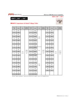
1 EIA Low ESR Microwave Capacitors0603N (.060"x .030") 0603N Capacitance & Rated Voltage TableRemark: special capacitance, tolerance and WVDC are available, consult with PASSIVE (.060"x .030") ,B,C, ,B,C,D250 VCode25116160F,G,J, , B, ,G,J, Low ESR Microwave Capacitors0603N (.060 x .030 ) Part Numbering0603N101JW251 Rated VoltageSeriesRated Capacitance *(See capacitance table)Capacitance Tolerance(See capacitance table) 0603N Chip Dimensionsunit: inch (millimeter)* When capacitance is less than , use R for decimal Design KitsCapacitance ToleranceCodeABCDFGJKTol. 1% 2% 5% 10% .006( ).032 .006( ).030 .005~ ( + ~ ).014 .006 ( )Sn/Ni(RoHS)KitDescriptionValuesToleranc eDKD0603N010603N .1pF , , , , , , , , , , , , , , , + DKD0603N020603N , , , , , , , , , , , , , , , +/.
2 1pF10pF +/-5% DKD0603N030603N 10 -100pF10, 12, 15, 18, 20, 22, 24, 27, 30, 33, 39, 47, 56, 68, 82, 100pF +/-5%LcWcBTcThese Capacitors are 100% RoHS. Kits are available that contain 10 (ten) pieces per value; number of values per kit varies, depending on case size and capacitance. Termination Types:W = Nickel,Plated 100%Sn(RoHS)L = Tin/Lead (90%Sn10%Pb) Also Available in Tin/Lead Termination (90%Sn10%Pb)PPI0603 NDATA122018 RevAEIA Low ESR Microwave Capacitors0603N (.060 x .030 ) Environmental TestsItemSpecificationsInsulation Resistance (IR)105 Megohms min. @ +25 Cat rated Megohms min. @ +125 Cat rated Voltage250 VDielectric Withstanding Voltage (DWV)250% of rated Voltage for 5 Temperature Range-55 Cto +175 CTemperature coefficient (TC)0 30ppm/ CCapacitance Drift or , whichever is EffectsNone PerformanceItemSpecificationsMethodTermi nalAdhesionTermination should not pull off.
3 Ceramic should remain pull force exerted on axial leads soldered toeach terminal. mechanical damageCapacitance change: ~+ > >10 G OhmsBreakdown voltage: x WVDCP reheat device to 150 C-180 Cfor 60 in 260 C 5 Csolder for 10 1 after 24 2 hour cooling mechanical damageCapacitance change: or maxQ> >10 G OhmsBreakdown voltage: x WVDCMIL-STD-202, Method 107, Condition the maximum rated temperature(-55 Cand175 C)stay 30 time of removing shall not be more than 3 the five ,SteadyStateNo mechanical damageCapacitance change: or > >1 G OhmsBreakdown voltage: x WVDCMIL-STD-202, Method VoltageHumidityNo mechanical damageCapacitance change: or > >1 G OhmsBreakdown voltage.
4 X WVDCMIL-STD-202, Method 103, Condition A, with Volts applied while subjected to an environmentof85 Cwith 85% relative humidity for 240 hours mechanical damageCapacitance change: or > >1 G OhmsBreakdown voltage: x WVDCMIL-STD-202, Method 108, for 1000 hours, at 175 Rated voltage Factor (Q)2,000 min. @ 1 MHzPPI0603 NDATA122018 RevAEIA Low ESR Microwave Capacitors0603N (.060 x .030 ) 0603N Electrical Performance CurvesESR vs. FrequencyFirst Parallel Resonant Frequency vs. CapacitanceThe First ParallelResonance, FPR,isdefinedasthe lowest frequencyat which a suckout or notch appearsin|S21|.It is generallyindependentof substrate thickness or dielectric constant, but does depend on capacitor orientation.
5 A horizontal orientation meansthe capacitor electrode planes are paralleltothe planeof the Low ESR Microwave Capacitors0603N (.060 x .030 )First Series Resonant Frequency vs. CapacitanceDefinitionsandMeasurementcond itions:Alldatahasbeenderivedfromelectric almodelscreatedbyModelithics,Inc., can be found on the PPI Website-- onthechartsarefor acapacitorina series configuration, , mounted across agapina microstrip trace with a conditionsare: substrate -- RogersRT/duroid 5880; substrate dielectric constant = ; substrate thickness (mils) = 10;gapinmicrostrip trace (mils) = ; microstrip trace width (mils) = ;Reference planes First Series Resonance,FSR, is defined as the lowest frequency at which the imaginary part of the input impedance, Im[Zin],equals zero.
6 Should Im[Zin] or the real part of the input impedance, Re[Zin], not be monotonic with frequencyat frequencies lower than thoseatwhich Im[Zin] = 0,theFSR shall be considered as undefined. FSRis dependent on internal capacitor structure; substrate thickness and dielectric constant; capacitor orientation, as defined alongside theFPRplot; and mounting pad (.060 ) Tape & Reel Specifications Horizontal Orientation Horizontal Mounting Recommended Land Pattern DimensionsWhen mounting the capacitor to substrate, it's important to carefully consider that the amount of solder (size of fillet) used has a direct effect upon the capacitor once it's )Thegreatertheamountofsolder, ) In the situation where two or more devices are mounted onto a common land, be sure to separate the device into exclusive pads by using soldering Low ESR Microwave CapacitorsPPI0603 NDATA122018 RevA