Transcription of TP-0887 Revised 01-11 Trailer ABS with Roll Stability ...
1 TP-0887 Revised 08-18 Installation GuideTrailer ABS with Roll Stability Support (RSSplus ) for Constant Power Trailers with Air or Mechanical Suspensions2S/2M or 4S/2M with Roll Stability Support (RSS) Using RSSplus 480 107 000 0TP-0887 Revised 08-181 Installation Guide and Service InformationBefore You and understand all instructions and procedures before you begin to service and observe all Warning and Caution hazard alert messages in this publication. They provide information that can help prevent serious personal injury, damage to components, or your company s maintenance and service, installation, and diagnostics special tools when required to help avoid serious personal injury and damage to Alert Definitions and Torque SymbolsWARNINGA Warning alerts you to an instruction or procedure that you must follow exactly to avoid serious personal injury and damage to Caution alerts you to an instruction or procedure that you must follow exactly to avoid damage to components.
2 @ This symbol alerts you to tighten fasteners to a specified torque Alert MessagesWARNINGTo prevent serious eye injury, always wear safe eye protection when you perform vehicle maintenance or the vehicle on a level surface. Block the wheels to prevent the vehicle from moving. Support the vehicle with safety stands. Do not work under a vehicle supported only by jacks. Jacks can slip and fall over. Serious personal injury and damage to components can voltages can damage the electronic control unit (ECU). Disconnect all connectors from the ECU before you perform any welding, electrostatic painting, or any other activity that applies high voltage to the vehicle frame. Install blind plugs into the ECU to protect the connector openings. Ground the welding or painting equipment to the part you are working on. If you are working on a moving or insulated component such as an axle, make sure it is correctly grounded through the frame. Refer to the equipment manufacturer s recommended instructions for correct the Trailer has correct electrical grounding.
3 Refer to SAE Specification you require technical assistance, contact WABCO North America Customer Care at 855-228-3203. Technical publications for all WABCO products are available on our is an advanced vehicle control system from WABCO that reduces chances of a rollover and assists the driver in maintaining control of the vehicle. However, any vehicle may overturn in some situations with or without RSSplus does not allow drivers to take unnecessary risks. Make sure drivers do not take curves or turns faster than they would without RSSplus and always use safe driving techniques. Failure to do so can result in serious personal injury, damage to components, or both. An alert unimpaired driver remains the primary element in maintaining control of the vehicle and reducing the chances of rollover s roll Stability support provides an independent Stability system for single, tandem or tri-axle constant-powered trailers equipped with air or mechanical suspensions.
4 It is compatible with both disc and drum foundation brakes. The system consists of: TP-0887 Revised 08-18(16579)Page 2 Copyright WABCO, Inc., 2018 Printed in USA An electronic control unit (ECU)/dual modulator valve assembly with built-in pressure sensors to monitor control and supply pressure, as well as axle load. A lateral accelerometer incorporated into the ECU monitors Trailer Stability . RSSplus ECU is fully serviceable with NPTF threads. PLC communication fully integrated Two or four wheel speed sensors J1708/1587 diagnostic cable (optional) External control line pressure sensor and cable (optional) WABCO diagnostics incorporated into WABCO TOOLBOX Software Easy-to-use blink codes Five generic inputs/outputs, three digital and two analogTrailer Configurations This installation guide covers 2S/2M or 4S/2M Trailer ABS with RSSplus installations. Sensor installation procedures are based on using ABS-prepped axles. RSS for 2S/1M configurations are not covered in this manual.
5 RSS is permitted on B-train configurations. An RSS system is strongly advised on both trailers in this configuration, as this configuration provides maximum Stability support. Contact your WABCO representative for additional information relating to pneumatic considerations for this configuration. Double and triple Trailer applications must be pre-approved by WABCO. Application approval forms can be found under Literature at Proportioning Function InformationAll RSSplus ECUs have load proportioned default settings. Trailer braking is less aggressive when the Trailer is unladen, resulting in increased brake lining life. If Trailer specific load proportioning is desired, please contact WABCO North America Customer Care at 855-228-3203 for assistance. If no proportioning is desired, the unladen braking pressures may be changed with TOOLBOX Software. The administration of these parameters is covered in the Parameter Entry System Requirements A WABCO Trailer in-line filter (or WABCO gladhand with integrated filter) is required for ALL RSS installations and is to be installed in the control line, upstream of the RSS ECU/dual modulator valve assembly.
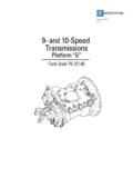
6 For correct ABS and RSS functionality, LED brake lights must be used. To complete the RSSplus installation, you must have 120 psi air pressure available. A 12-volt DC (10 amp minimum) power supply must also be available. For diagnostics or installation testing, ensure only constant power (blue pin) is applied. Do not apply power to the stoplight circuit (red pin).NOTE: Blink codes for level one diagnostics are a standard capability for the RSS ECU. In-depth level two diagnostics are available in WABCO TOOLBOX DefinitionsThese features are integrated into the RSS b l e ARSS plus ComponentsECU/Dual Modulator Valve AssemblyThe valve portion of the Electronic Control Unit (ECU)/dual modulator valve assembly contains two separate modulator valves. Each valve has its own delivery ports, three per valve. Therefore, the mounting orientation whether the valve is mounted with the sensors facing the front or the rear of the Trailer determines sensor hookup. Figure 1, Figure 2 and Figure 3.
7 Mounted with sensors facing front of Trailer : The f and d sensor connections go to the curbside and the c and e connections go to the AccelerometerA sensing device that monitors differences in acceleration from side to Line Pressure SensorA sensor that measures the control line pressure. Where Trailer timing response improvement is needed, an external pressure sensor may be Load Pressure SensorA pressure sensor with a pneumatic port for the air suspension that provides load measurement for the Pressure SensorA sensor that monitors the Trailer supply pressure and triggers a warning lamp if the pressure drops below 66 psi ( bar). TP-0887 (16579) Revised 08-18 Printed in USAC opyright WABCO, Inc., 2018 Page 3 Mounted with sensors facing rear of Trailer : The c and e connections go to the curbside and the f and d sensor connections go to the 1 Figure 2 Figure 3 RSS SoftwareNOTE: Complete RSS software programming instructions are included in this of line testing is required on all Trailer RSS installations.
8 Use WABCO TOOLBOX Software to perform this test. This software must be available at all Trailer manufacturers where RSS is being installed. If you do not have this software program, please contact WABCO North America Customer Care at 855-228-3203. Do not begin the RSS installation if you do not have this of line testing must be completed before the Trailer is released into service. The RSS portion of TOOLBOX Software is used to conduct the will not function if the mounting location does not meet the following not mount the ECU/dual modulator valve assembly facing sideways. The ECU/dual modulator valve assembly must be mounted facing the front or rear of the not tank mount. An air tank will not support the weight of the ECU/dual modulator valve assembly and may result in damage to the air tank. A bracket may be fabricated using steel at least 3/16-inch (4 mm) thick or mounted directly to the cross member. Figure Requirements for Air SuspensionsThe ECU/dual modulator valve assembly contains a lateral accelerometer that provides data for Stability control.
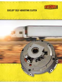
9 For optimum lateral accelerometer function, the ECU must be mounted level to a rigid structure of the subframe in the center of the width of the Trailer , midway between the axle spacing. Figure : A barrier of plastic or mylar should be placed between the ECU valve assembly and the surface it will be mounted on. This will help inhibit potential corrosion between dissimilar 1 Figure 2 Figure 3 4006865aGI05GI04GI03GI0GI01fd4121 CONTROLLINE PORTAIRSUSPENSIONPORT+EXHAUSTSUPPLYSENSO R FSENSOR EPOWEREXTERNALMODULATORVA LV EMOUNTINGBOLTSSENSOR 08-18(16579)Page 4 Copyright WABCO, Inc., 2018 Printed in USAF igure 4 PreparationBefore beginning the installation procedure, perform the the ECU/dual modulator valve assembly for damage that may have occurred during shipping or storage. Look for crushed or bent connectors. Verify that the yellow retainer clips have not been bent or otherwise damaged. Do not install a damaged ECU/dual modulator valve assembly. Notify your supervisor, or contact WABCO if there is any apparent that the following installation components are Components ECU/dual modulator valve assembly RSSplus power cable J1708/1587 diagnostic cable (optional) External control line pressure sensor and cable (optional) Sensor extension cables, two pieces for 2S systems, four pieces for 4S systems Sensors, two or four, for non-ABS-prepped axles WABCO Trailer ABS in-line filter WABCO TOOLBOX Software version or higher ABS indicator label, TP-95172 Constant power label (part number 899 201 833 4)Non-WABCO Components Minimum 5/8-inch nylon tubing for supply 3/8-inch nylon tubing for axle load sensor SAE standard, DOT-approved thread sealant Incandescent-type DOT-approved lamp, or an LED with integral load resistor 1/2-inch grade 8 nuts and washersFigure 44005548b 3 3 15 CENTER OFAXLE SUPPORTZZYYXX ( 2000 MM)
10 Y-direction from the vehicle longitudinal axisX-longitudinal direction from the center of the axle supportTilt of the ECU/dual modulator valve assembly around the X-axis (roll angle)Tilt of the ECU/dual modulator valve assembly around the Y-axisRotation of the ECU/dual modulator valve assembly around the Z-axis (yaw angle) Inches ( 500 MM) Inches ( 2000 MM) 3 Degrees 15 Degrees 3 DegreesLocation or Mounting PositionPermissible Maximum Deviation "( 500 MM) TP-0887 (16579) Revised 08-18 Printed in USAC opyright WABCO, Inc., 2018 Page 5 Component InstallationECU/Dual Modulator Valve AssemblyCAUTIONDo not tank mount. An air tank will not support the weight of the ECU/dual modulator valve assembly and may result in damage to the air tank. A bracket may be fabricated using steel at least 3/16-inch (4 mm) thick or mounted directly to the cross member. Figure will not function correctly if the mounting location does not meet the following requirements. To complete the RSSplus installation, you must have 120 psi air pressure available.