Transcription of How to select Rotary Lobe Pumps - …
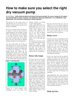
1 How to select Rotary lobe Pumps ZL Series 2008 de Rotary lobe Pumps HOW TO select Rotary lobe Pumps Water performance selection: Step 1 Speed, rpm Starting from the vertical left hand (flow rate) axis, at the required capacity, plot a line horizontally across to intersect the solid flow/speed performance lines at the differential pressure. At this intersection, plot a line vertically down to the bottom speed axis and read off the pump rpm. Step 2 Power, kW Commencing again from the left hand (flow rate) axis, at the specified capacity, plot a line horizontally across to intersect the dotted flow/absorbed power lines at the differential pressure. At this intersection plot a line vertically upwards to the top absorbed power axis and read off the absorbed kW. WATER CAPACITY AND ABSORBED POWER GRAPH Performance curve model ZL-220-34-12. FLOW LPMDIFFERENTIAL PRESSURE BAR ABSORBED POWER Kw SPEED RPM ABSORBED POWER FIGURES ARE FOR 1 cP VISCOSITY VISCOSITY CORRECTION cP Rotary lobe Pumps For example, 50 LPM, 1 cP against a differential pressure of 3 bar, using a ZL-220 lobe pump: Steep 1 Speed Working from the flow axis at 50 LPM dotted a line horizontally across to intersect the dotted 3 bar, between the 2 bar and 4 bar flow/speed performance lines.
2 Plotting vertically down from this intersection the pump rpm can be read off the speed axis equal to 320 rpm. Steep 2 Power Starting from 50 LPM on the flow rate axis dotted a line horizontally across to intersect the dotted 3 bar, between the 2 bar and 4 bar flow/absorbed power lines. At this intersection dotted a line vertically upwards to the brake horsepower axis and read off the absorbed kW of Viscosity liquid performance selection: Steep 1 Speed, rpm When handling other than water-like liquids the viscosity correction monogram at the top of the performance graph (capacity vs. speed lines) should be used. Case 1: If viscosity of 1 cP, differential pressure 12 bar then, select the pump speed from the bottom 12 bar line. Case 2: If viscosity of 300 cP, differential pressure 6 bar then, select the pump speed from the 0 bar line. Case 3: If viscosity of 20 cP, differential pressure 8 bar then, select the pump speed from the 2 bar line.
3 It can be seen from the graph ZL-220/34/12 that when exceeding 300 cP the slip in the pump is negligible and the 0 pressure line can be used for any differential pressure. Steep 2 Power, kW To calculate the total power absorbed to move the fluid with different viscosities from water, it is necessary to determinate the viscosity factor V . Use the next table and future formula to calculate the power. Rotary lobe Pumps Graph to determinate the viscosity factor. Use the next formula to calculate the power: ()()10002 ZLCnVPN + = Where: P = Pressure 2cmkg V = Viscosity factor n = Speed (rpm) C = Flow ()revlt As we know the capacities per revolution of each model from the ZL series, now we can select and determinate the size of the pump: ZL 110 115 120 220 225 330 340 440 450 CZL Viscosity cPViscosityfactor V Rotary lobe Pumps select from the table using the viscosity, the maximum recommended speed for each pump size.
4 Model 110 115 120 220 225 330 340 440 450 Viscosity (cP) Max. Recommended speed rpm 1 - 100 1000 800 800 700 700 600 600 500 500 100 - 1,000 667 533 533 467 467 400 400 333 333 1,000 - 5,000 417 333 333 292 292 250 250 208 208 5,000 - 10,000 250 200 200 175 175 150 150 125 125 10,000 - 20,000 167 133 133 117 117 100 100 83 83 20,000 - 50,000 117 93 93 82 82 70 70 58 58 50,000 - 100,000 83 67 67 58 58 50 50 42 42 Example: select a Rotary lobe Pump with the next characteristics: cream at 2000 cP, flow required of 70 LPM, against a differential pressure of 8 kg/cm2. To calculate the pump speed in rpm, divide the 70 LPM among each model s capacity per revolution: Model ZL 110 115 120 220 225 330 340 440 450 CZL 0,05 0,12 0,21 0,40 0,62 1,02 1,44 2,27 3,34 Speed rpm 1400 583 333 175 113 69 49 31 21 Compare every pump model and determinate the best choice, using the maximum recommended speed.
5 For this case, a ZL120 pump is the best choice with a speed of 333 rpm. To calculate the power use the formula using the data: P = 8 2cmkg V(2000 cP) = n = 333 (rpm) CZL(ZL120) = ()revlt ()()= + = Kw Rotary lobe Pumps QUESTIONNAIRE Customer: _____ _____ Date:_____ Quantity: _____ set Pumps /Blender: Model no. _____ Capacity: _____ Units _____ Pressure head: _____ Units _____ Impeller diameter: _____ Units _____ Product: _____ Specific gravity: _____ Units _____ Concentration: _____ Units _____ Viscosity: _____ Units _____ Temperature _____ Units _____ Hard particles: _____ Mechanical seal (shaft seal) Seat ring: Ceramic _____ SiC _____ TC _____ Rotary ring: Carbon _____ SiC _____ TC _____ O-rings: NBR _____ EPDM _____ Viton _____ Water flushing: Yes _____ No _____ Electric motor Power: _____ RPM _____ Hz _____ Volt _____ Type: TEFC _____ EG3 _____ D2G4 _____ Without motor Yes _____ No _____ Connections Inlet: Dimension: _____ Type: _____ Outlet: Dimension: _____ Type: _____ Special design Drain on casing version: Yes _____ No _____ Position no _____ Base mounting version: Yes _____ No _____ Frame mounting version: Yes _____ No _____ Transportable version: Yes _____ No _____ Remarks.
6 _____ _____ _____ _____ _____ Signature