Transcription of Deriving Life Multipliers for Electrolytic Capacitors
1 1 Deriving life Multipliers for Electrolytic CapacitorsSam G. Parler, Jr., Dubilier140 Technology PlaceLiberty, SC Aluminum Electrolytic Capacitors are routinelyused as input bus Capacitors in the power supplysections of electronic equipment such as motordrives, UPS systems, and welders. Most of thesecapacitors fail eventually from wearout. This ar-ticle offers a brief explanation of how capacitormanufacturers quantify the effects of applied volt-age, ripple current, frequency, ambient tempera-ture, and airflow on capacitor life . The general capacitor life equation isL = LB f1(TM TC) f2(V) (1)where L is the life estimate in hours, LB is the baselife at elevated maximum core temperature TM, TCis the actual core temperature in the application ofinterest, and V is the applied DC voltage.
2 This equa-tion shows that there are three factors in the lifeequation: base life , temperature, and DC voltage. Base life LB is the expected service life at fullrated voltage and temperature TM. A typical ratingis LB = 5,000 hours at TM = 108 C. End of life isusually defined in terms of parametric changes incapacitance, effective series resistance (ESR), andleakage current. One of the most recent industryefforts for standardizing these tests and limits waspublished by the EIA and is available as EIA IS-749. The effect of temperature on capacitor life is dic-tated by the Law of Arrhenius, which is (2)( )Eakf1 = e 1TC 1TM ( )TM TCEak = eTCTMFor anodic alumina the activation energy Ea = The Boltzmann constant k = eV/K, sowe have Ea/k = K.
3 The Arrhenius equa-tion for the temperature life factor f1 may be re-arranged as follows to establish the familiar doubles every 10 C rule. If we define T = TM-TC and choose TCTM based on the normally highestusage Electrolytic temperature range of 125 C (398K), we have > 1 (3) The temperature rise T is calculated as T = P = I2R (4)T10( ) (398)2f1 = e e ln2 T / 10= 2 T / 10where P is the dissipated power, I is the AC RMSripple current, R is the ESR, and is the thermalresistance from core to ambient, which is the sumof the core-to-case thermal resistance CC and thecase-to-ambient thermal resistance CA. = CC + CA CC + 500A-7/8(v+1)-2/3 (5)where A is the surface area of the capacitor (cm2)and v is the airflow velocity (m/s) near the capaci-tor.
4 A fairly good model for the ESR isR = RS(TC) + D/2 fC (6)where RS is the ohmic loss from electrolyte, tabsand foils, and D/2 fC is the dielectric loss D isthe dissipation factor D , f is the frequency(Hz), and C is the capacitance (F). RS usually pos-sesses a significant negative temperature coeffi-cient (1-2% per C near room temperature) due tothe electrolyte viscosity s change with temperatureand its associated effect on the ionic mobility ofthe conductive species within the electrolyte. Dusually has a positive temperature coefficient( C is typical). The voltage multiplier f2 arises from the loweredstress on the dielectric when the applied DC volt-age Va is reduced. In Electrolytic Capacitors , ap-plying DC voltage actually drives a beneficial, on-going electrochemical reaction that heals defectsin the anode dielectric.
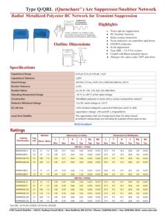
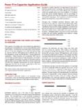
5 However, at higher stresslevels such as when the temperature is near TM ,the additional leakage current from operating near Published in the IEEE Power Electronics Society Newsletter, vol. 16, no. 1, Feb. 2004, pp. 11-12 2 Published in the IEEE Power Electronics Society Newsletter, vol. 16, no. 1, Feb. 2004, pp. 11-12the maximum voltage rating Vr may cause enoughelectrochemical degradation and hydrogen gas evo-lution as to reduce the life of the capacitor. There-fore a reduction in the applied DC voltage mayextend the life of the capacitor, especially at el-evated temperatures in Capacitors that are tightlysealed. The effect of voltage derating on life hasbeen modeled with linear fit and with power lawsof the voltage ratio x=Va/Vr with exponents from0 (no effect) to 6.
6 See Figure 1. From these equations we can readily derive lifeor ripple current Multipliers for derated ambienttemperature, derated ripple current, airspeeds otherthan natural convection, and frequencies other thanthe standard 100 or 120 Hz, starting with the ca-pacitance, ESR, and ripple current ratings. Remem-ber not to try to have your cake and eat it, too byusing both the life and ripple Multipliers simulta-neously! The ripple Multipliers are approximatelyas follows:Ambient temperature (7)Frequency (8)Air speed (9) CC + 500A-7/8(v+1)-2/3 CC + 500A-7/8(vR+1)-2/3RS + D/2 fRCRS + D/2 fCTM TATM TR Large core-to-ambient temperature rises fromhigh ripple current shorten life more than (7) sug-gests because increasing ESR accelerates the tem-perature rise.
7 In these equations, TR is the ratedambient temperature at which the rated ripple isspecified, fR is the frequency of the rated ripple,and vR is the rated air velocity (usually 0-1 m/s).Figure 2 shows calculated life Multipliers for thecase of a 270 F 400 Vdc snapmount capacitorversus f & (Ia/Ir) and versus v & 1: DC voltage life Multipliers from various capaci-tor manufacturers. CDE generally uses G. Parler, Jr., , was born inSouth Carolina, USA, in 1961 andstudied electrical engineering atClemson University. After receiving hisBSEE degree in 1984, he worked forUnion Switch & Signal. From 1988 to1991 he directed a Strategic DefenseInitiative contract for Cornell Dubilier, developing highenergy density Capacitors for military applications.
8 In 1994he co-founded Maven Capacitor Corporation (presentlyowned by St. Jude Medical) to develop and produce highenergy density aluminum Electrolytic pulse Capacitors forimplantable defibrillators. Mr. Parler has served as Directorof Research and Development for Cornell Dubilier since1996. His topics of capacitor research include thermalmodeling, impedance modeling, life and reliability modeling,and ways to improve capacitor 2: life Multipliers demonstrating the effects ofvarying ripple amplitude and frequency (top) and varyingair speed and ambient temperature (bottom).