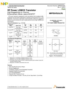
Transcription of P&E Microcomputer Systems, Inc. - NXP …
1 2010 P&E Microcomputer Systems, , Qorivva, and ColdFire are registered trademarks of Freescale Semiconductor, Microcomputer Systems, Summary For USB Multilink Universal, Rev. A(PART# USB-ML-UNIVERSAL)Supports Freescale: RS08 HCS08 HC(S)12(X) S12Z ColdFire V1/ColdFire+ V1 ColdFire V2-4 Qorivva MPC55xx/56xx Kinetis Power Architecture PX Series DSCD ocument# PE4534, Version Introduction2. Usage of the USB Multilink Universal3. Driver Installation On Windows XP/2000/2003/Vista/74. Connecting To The Target5. Startup Reset Sequence6. Firmware Updates/Architecture Selection7. Interface Libraries8. Compatible Software9. Transition To Production Programming1 IntroductionP&E s USB Multilink Universal interface provides access to debug modes on a wide range of Freescale microcontroller families by communicating between the debug header on a target, and a USB port on a computer. The families of Freescale microcontrollers are supported via the multiple headers located on the USB Multilink Universal.
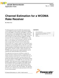
2 The headers for Ports A-D are dual-row with a .100 pitch, and the headers for Ports F-G are dual-row with a .050 pitch. The pin-outs for these connections and the families that they support are shown below. Please note that Port G, the Kinetis mini-10 connector, is supported but there is no corresponding ribbon cable included. Port E, the 16-pin JTAG/COP connector, is not currently supported. Figure 1-1: USB Multilink Universal HeadersBy using the USB Multilink Universal, the user can take advantage of debug modes to halt normal processor execution and use a computer to control the processor. The user can then directly control the target's execution, read/write registers and memory values, debug code on the processor, and program internal or external FLASH memory devices. Technical Summary For USB-ML-UNIVERSAL Rev. A2 Usage Of The USB Multilink Universal InterfaceThe USB Multilink Universal can communicate with RS08, HCS08, HC(S)12(X), S12Z, ColdFire V1/V2/V3/V4, Qorivva MPC55xx/56xx, DSC, Power Architecture PX Series, and Kinetis microprocessors by connecting a ribbon cable between the target's debug header and one of the multiple ports on the USB Multilink Universal.
3 Do not attempt to use multiple ports at once, as this may damage both the target processors as well as the USB Multilink USB Multilink Universal Interface will work with targets whose processor power supply is in the range of to The interface derives its power from the USB port and draws less than 1mA from the target. The USB Multilink Universal has a female type B USB connector. Use a Type A to Type B male-to-male USB cable to connect the interface to the USB Multilink Universal is a USB device. If a USB Hub is used, it must be a self-powered hub ( with its own power supply). By default, the USB protocol used is USB are two LEDs on the USB Multilink Universal interface. The blue LED indicates that the interface is powered and running. The yellow LED indicates that target power has been :If connecting to a ColdFire V2-4 processor which requires synchronous communication, such as the MCF5272 and MCF5206(E), a CABLE-CF-ADAPTER (sold separately) is :To avoid improper connections, the red stripe of the ribbon cable should always be oriented towards Pin 1, both on the Multilink port and the target processor 2-1: Proper orientation of ribbon cables3 Driver Installation On Windows XP/2000/2003/Vista/7 Before connecting the USB Multilink Universal to the PC, the appropriate drivers need to be installed on the PC.
4 These drivers are automatically installed when installing Freescale s CodeWarrior or any of P&E s recent software development packages. If you have installed a recent version of these then the instructions for manual installation that follow are not necessary. However, Windows 7 users who are installing software distributed before December 28, 2009 will need to obtain the latest version of the drivers and install them manually. A copy of the driver installation program may be downloaded from the Downloads section of P&E s Support Center located at If you are using third-party software, make sure you have a version which supports the USB Multilink Universal Rev. A interface. Once you have obtained the latest version of the driver installation program, please use the instructions below to manually install the the cable is plugged in, the operating system should indicate that it has found a driver for the attached interface.
5 Follow the instructions in the Found New Hardware Wizard dialog for having Windows automatically install the you connected the Multilink interface prior to installing the drivers, Windows will not have been able to find the appropriate driver and may have disabled the device. If you unplug the device and then plug it in again, Windows will automatically disable it even if you have installed the drivers. To force Windows to attempt to load the driver Technical Summary For USB-ML-UNIVERSAL Rev. Aagain, perform the following steps while the USB Multilink Universal interface is plugged into the the Control Panel: Start Button [ ->Settings ] ->Control Panel. (You will not need to select Settings on Vista and Windows 7). Click the system Icon. (Windows 7: system and Security ) the Hardware Tab. (Windows 7: Hardware and Sound , Windows Vista: skip this step) the Device Manager Button. (Windows 7: Devices and Printers -> Device Manager ) USB Multilink device will be shown with an exclamation point next to it.
6 Double-click this the Reinstall button and follow the dialog instructions to have Windows automatically install the driver. (Windows 7: First click the Driver tab, then select Update ) the hardware still has a yellow exclamation mark next to it, right click on it and select uninstall. The USB Multilink should disappear from the list. Unplug the USB Multilink and then plug it into the PC again. A new Hardware Found dialog will pop up; follow the dialog instructions and have Windows automatically install the To The TargetThe following is the proper connection sequence to connect the PC to the target system via the USB Multilink Universal sure the target power is OFF and the USB Multilink Universal is not connected to either the target or the the Multilink and connect a ribbon cable from the correct Multilink port to the target. Make sure that the ribbon cable is plugged into the target with the proper orientation.
7 PIN 1 is indicated by a 1 next to the the USB Multilink to the PC via a USB cable. The Blue LED on the Multilink should become the target power on. The Yellow LED on the Multilink should become disconnecting the setup, turn the target power Reset SequenceNote that if the device does not enter debug mode, the program issues the error message Cannot enter background mode. If you receive this message you should check your hardware with a scope, logic analyzer or logic probe. First check for power on, then check to make sure the processor oscillator is running. Finally, look for the startup sequence for your microprocessor that is listed A JTAG/ONCE Qorivva MPC55xx/56xx, Power Architecture PX Series, DSCa. RESET (Pin-9) is driven low (to processor).b. Activity appears on TCLK (Pin-5), TDI (Pin-1) and TDO (Pin-3). (PC software instructs the processor to enable debug mode). c. RESET (Pin-9) is released by the interface and will go Activity appears on TCLK (Pin-5), TDI (Pin-1) and TDO (Pin-3).
8 (Debug activity).Ports B, F, G ARM JTAG Kinetisa. RESET is driven low (to processor).b. Activity appears on TCLK, TDI and TDO (PC software instructs the processor to enable debug mode). c. RESET is released by the interface and will go Activity appears on TCLK , TDI and TDO (Debug activity).Port C BDMRS08, HCS08, S12Z, ColdFire V1a. Debug activity is seen on BKGD (Pin-1).Technical Summary For USB-ML-UNIVERSAL Rev. AHC12a. BKGD (Pin-1) and RESET (Pin-4) are pulled low by the After 5 milliseconds, RESET (Pin-4) is released and goes After 10 milliseconds, BKGD (Pin-1) is released and goes After 20 more milliseconds, debug activity is seen on BKGD (Pin-1).Port D Coldfire V2/V3/V4a. BKPT (Pin-2), DSI (Pin-8), and DSCLK (Pin-4) signals are driven low. b. RESET (Pin-7) is driven low for 20+ milliseconds and released. c. After RESET is released and if the processor has correctly entered background mode, the PST0 (Pin-15), PST1 (Pin-14), PST2 (Pin-13) and PST3 (Pin-12) lines should all be driven high by the processor.
9 D. Activity (changing signals) is seen on the DSI, DSO, and DSCLK signals. The activity on the DSCLK and DSI lines is generated by the PC and the activity on the DSO line is generated by the processor. Port E JTAG/COP (Not yet supported)6 Firmware Updates/Architecture SelectionThe USB Multilink Universal uses firmware updates to change between modes of operation to support different families of Freescale microcontrollers. Older versions of P&E's software and Freescale's CodeWarrior are not able to automatically configure the USB Multilink Universal when the target is switched to a different family of microcontrollers. If you are not using the latest version, please contact us to determine if you are eligible for a discounted upgrade to the latest version of P&E software. You may also download a manual configuration utility for the USB Multilink Universal from the Support Center or USB Multilink Universal product page on our website: LibrariesP&E produces a set of interface libraries which allow the user to directly control the USB Multilink Universal from any Windows Development environment which can interact with a DLL.
10 The interface libraries come with examples for controlling the Multilink interface from Microsoft Visual C as well as Borland Delphi. More details can be found on the Interface Libraries page on the P&E website: SoftwareIn addition to support from Freescale Codewarrior and other third party software, each of the families supported by the USB Multilink Universal is supported by a variety of software from P&E, including flash programmers, debuggers, and test application packages . Details can be found in the Products section at To Production ProgrammingThe USB Multilink Universal is intended for development and is not designed to accomodate the demands of production programming. However, P&E s Cyclone programmers are specifically engineered to withstand the rigors of a production environment and will provide a seamless transition from the USB Multilink Universal. More information is available at: USB Multilink Universal Interface - Coming SoonP&E is developing a high-speed version of the USB Multilink Universal called the USB Multilink Universal FX.