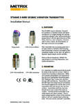
Transcription of 162 VTS SLIM VIBRATION TRANSMITTER
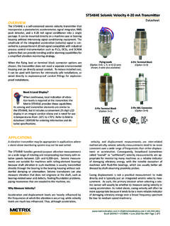
1 # 1004597 REV F (August 2014) Page 1 of 2 162 VTS slim VIBRATION TRANSMITTERD atasheetC USOVERVIEWThe 162 VTS is the ideal solution for sensing VIBRATION on most plant equipment. It generates a two-wire loop signal propor-tional to velocity for transfer to a programmable logic controller (PLC), distributed control system (DCS) or other 4-20 mA input devices. Simply mount the TRANSMITTER on the machine case, connect the 2-wire loop and read and/or record the VIBRATION . FEATURES Loop terminals w/Independent Polarity (IPT ) Interfaces with PLC, DCS, 4-20 mA monitors, etc.
2 Different mounting studs available Flying leads or terminal block connector Most stable detection circuit available Ski slope problem protected Built-in base & housing strain protection Improved shielding and stabilityAPPLICATIONS Blowers Centrifuges Compressors Engines Fans Generators Motors Pumps Steam Turbines TurbochargersSPECIFICATIONS VIBRATION Range4 to 20 mA output proportional to velocity. Refer to Ordering Op-tion A for ranges. Nonstandard ranges ResponseStandard: 2 - 1500 HzAxis OrientationAnySupply Voltage (Vs)11-30 VDC, Non-polarity sensitive, IPT Isolation500 Vrms, circuit to caseElectrical Connection2 pin terminal block (accepts up to 16 AWG wire).
3 A cable gland is also Load Resistance (RL)RL =50 x (Vsupply-11) ohms Service Temp. Rating-40 C to 120 C (T4A) (-40 C to 248 F)Enclosure Materials303 SSEnclosure Environmental RatingNEMA 4X, IP 65, IP 67 for 2 pin terminal block or flying lead option availableAgency ApprovalsRefer to Ordering Option C Internal View - 2 pinTerminal BlockHAZARDOUS AREAVERSIONNON-HAZARDOUS # 1004597 REV F (August 2014) Page 2 of 2 1/2 NPT male [ ] [ ]MOUNTING STUD1/4 - 18 NPT(STANDARD) [ ]OPTIONAL CONDUIT ELBOW & REDUCER, MODEL 91174-036, 1/2 NPT149 [ ]031 WEIGHTS AND DIMENSIONSM odel 162 VTS12 Current Measuring CircuitCustomer current-sensing resistor4-20 mAcurrent loop+-DC Power SupplyORDERING INFORMATION162 VTS slim VIBRATION TRANSMITTERAAA-BCD-EFAFull Scale1 2 1 in/s ( mm/s) peak1 2 3 in/s ( mm/s) peak1 2 6 in/s ( mm/s) peak2 0 0 in/s ( mm/s) peak1 5 1 in/sec ( mm/s) true RMS1 5 3 in/sec ( mm/s) true RMS1 5 6 in/sec ( mm/s) true RMS2 3 0 in/sec ( mm/s)
4 True RMSBM ounting0 Integral 1/4 NPT2 3/8 - 24 UNF X 3/8 4 M8X 1 - 10 CHazardous Area Certification3 CSA US/C Class 1, (A, B, C & D), Div 2 (non-incendive)4 CSA US/C Class 1, Div 1, Grps B-D (explosion-proof) and Class 2, Div 1, Grps E, F, G (dust-ignition proof). Available on the 1/2 NPT Top only (D = 5)5 Non-Hazardous Area CertificationDConnection5 4-20 mA; 1/2 NPT top, 24 leads6 4-20 mA; 2 pin terminal block (C = 3)Example: 162-126-455-00= in/s ( mm/s) peak scale, with M8X 1-10 mounting, non-hazardous area cert and 4-20 mA; 1/2 NPT top, 24 leadsACCESSORIESP roductPart NumberConduit Elbow and Reducer91174-036 Conduit Elbow, Reducer, 3-position terminal block8200-004 Stainless Steel Flange Mount Adaptor7084-002 7084-005 Two-Wire Cable Assembly8169-75-002-XXXC able Gland93818-015 Ferrite Core10045800 Units: mm [in]Weight: kg ( lbs.)
5