Transcription of High Pulse Load Carbon Film Leaded Resistors - …
1 CBB Beyschlag Revision: 19-Jan-161 Document Number: 28736 For technical questions, contact: DOCUMENT IS SUBJECT TO CHANGE WITHOUT NOTICE. THE PRODUCTS DESCRIBED HEREIN AND THIS DOCUMENTARE SUBJECT TO SPECIFIC DISCLAIMERS, SET FORTH AT Pulse load Carbon film Leaded ResistorsCBB 0207 Leaded Resistors with advanced Pulse load capability, are the perfect choice for circuitries exposed to high levels of electromagnetic interference or electrostatic discharge. The Resistors can also be used to protect the circuitry of signal and mains input lines from surge pulses. Applications are in all fields of automotive, telecommunication and industrial Pulse load capability up to 6 kV or 140 W Specialty product for ESD and EMC sensitive applications Special Carbon film technology for maximum heat stress capability Material categorization: for definitions of compliance please see APPLICATIONS Automotive Telecommunication Industrial equipmentAPPLICATION INFORMATIONThe power dissipation on the resistor generates a temperature rise against the local ambient, depending on the heat flow support of the printed-circuit board (thermal resistance).
2 The rated dissipation applies only if the permitted film temperature is not exceeded. Furthermore, a high level of ambient temperature or of power dissipation may raise the temperature of the solder joint, hence special solder alloys or board materials may be required to maintain the reliability of the Resistors do not feature a limited lifetime when operated within the permissible limits. However, resistance value drift increasing over operating time may result in exceeding a limit acceptable to the specific application, thereby establishing a functional lifetime. The designer may estimate the performance of the particular resistor application or set certain load and temperature limits in order to maintain a desired SPECIFICATIONSDESCRIPTIONCBB 0207 Resistance range10 to M Res. Tolerance 2 %Temperature coefficientRefer to temperature coefficient graphRated dissipation, WOperating voltage, Umax.
3 AC/DC350 VMaximum permissible film temperature155 CMax. resistance change at P70 for resistance range, R/R after:10 to 100 k 1000 h 2 %8000 h+5 % / -4 %Permissible voltage against ambient (insulation):1 min; Uins500 VContinuous75 VFailure rate: FITobserved x 10-9/hCBB Beyschlag Revision: 19-Jan-162 Document Number: 28736 For technical questions, contact: DOCUMENT IS SUBJECT TO CHANGE WITHOUT NOTICE. THE PRODUCTS DESCRIBED HEREIN AND THIS DOCUMENTARE SUBJECT TO SPECIFIC DISCLAIMERS, SET FORTH AT (1)This TCR figure is exhibited by most ohmic values up to 10 k , for detailed information please see TCR curve on page RESISTANCE CHANGE AT RATED DISSIPATIONOPERATIONE MODESTANDARDPOWERC limatic category-55 C / +125 C / 56 days-55 C / +155 C / 56 daysRated dissipation, P70 CBB WApplied maximum film temperature, F C155 CMax. resistance change at rated dissipation | R/Rmax.
4 |, after:CBB 020710 to 100 k 1000 h (1 % R + ) (2 % R + )8000 h +(3 % R + )-(2 % R + ) +(5 % R + )-(4 % R + )TEMPERATURE COEFFICIENT AND RESISTANCE RANGETYPE / SIZETCRTOLERANCERESISTANCEE-SERIESCBB 0207-250 ppm/K (1) 2 %10 to M E24 PART NUMBER AND PRODUCT DESCRIPTIONPart Number: CBB0207001501GC100 TYPE / SIZESPECIAL CHARACTERTCRVALUETOLERANCEPACKAGINGSPECI ALCBB02070 = neutral0 = standardSee TCR graph3 digit value1 digit multiplierMultiplier9 = *10-10 = *1001 = *1012 = *1023 = *1034 = *104G = 2 %CTC1up to 2 digits00 = standardProduct Description: CBB 0207 2 % C1 1K5 CBB02072 %C11K5 TYPESIZETOLERANCEPACKAGINGRESISTANCE VALUECBB0207 2 %CTC147K = 47 k 51R1 = PACKAGINGTYPE / SIZECODEQUANTITYPACKAGING STYLEWIDTHPITCHDIMENSIONSCBB 0207CT5000 Taped acc. to IEC 60286-1fan-folded in a box52 mm5 mm77 mm x 82 mm x 324 mmC1100074 mm x 42 mm x 184 mmCBB0207001501GC1 00 CBB Beyschlag Revision: 19-Jan-163 Document Number: 28736 For technical questions, contact: DOCUMENT IS SUBJECT TO CHANGE WITHOUT NOTICE.
5 THE PRODUCTS DESCRIBED HEREIN AND THIS DOCUMENTARE SUBJECT TO SPECIFIC DISCLAIMERS, SET FORTH AT is strictly controlled and follows an extensive set of instructions established for reproducibility. A homogeneous and dense Carbon film is deposited on a high grade ceramic body (85 % Al2O3) and conditioned to achieve the desired temperature coefficient. Nickel plated steel termination caps are firmly pressed on the rods. A special laser is used to achieve the target value by smoothly cutting a helical groove in the resistive layer without damaging the ceramics. Connecting wires of electrolytic copper plated with 100 % tin are welded to the termination caps. The Resistors are covered by protective coating designed for electrical, mechanical and climatic protection. Five color code rings designate the resistance value and tolerance in accordance with IEC 60062 (1).
6 The result of the determined production is verified by an extensive testing procedure performed on 100 % of the individual Resistors . Only accepted products are stuck directly on the adhesive tapes in accordance with IEC Resistors are suitable for processing on automatic insertion equipment and cutting and bending machines. Excellent solderability is proven, even after extended storage. They are suitable for automatic soldering using wave or dipping. The encapsulation is resistant to all cleaning solvents (3) commonly used in the electronics industry, including alcohols, esters and aqueous solutions. The suitability of conformal coatings, potting compounds and their processes, if applied, shall be qualified by appropriate means to ensure the long-term stability of the whole system.
7 The Resistors are completely lead (Pb)-free, the pure tin plating provides compatibility with lead (Pb)-free and lead-containing soldering processes. The immunity of the plating against tin whisker growth has been proven under extensive acknowledges the following systems for the regulation of hazardous substances: IEC 62474, Material Declaration for Products of and for the Electrotechnical Industry, with the list of declarable substances given therein The Global Automotive Declarable Substance List (GADSL) (2) The REACH regulation (1907/2006/EC) and the related list of substances with very high concern (SVHC) (3) for its supply chainThe products do not contain any of the banned substances as per IEC 62474, GADSL, or the SVHC list, see Hence the products fully comply with the following directives.
8 2000/53/EC End-of-Life Vehicle Directive (ELV) and Annex II (ELV II) 2011/65/EU Restriction of the Use of Hazardous Substances Directive (RoHS) with amendment 2015/863/EU 2012/19/EU Waste Electrical and Electronic Equipment Directive (WEEE) vishay pursues the elimination of conflict minerals from its supply chain, see the Conflict Minerals Policy at applicable, the Resistors are tested in accordance with EN 140101-806 (successor of CECC 40101-806)which refers to EN 60115-1 and EN Beyschlag has achieved Approval of Manufacturer in accordance with IEC QC 001002-3, clause 2. The release certificate for Technology Approval Schedule in accordance with CECC 240001 based on IEC QC 001002-3, clause 6 is granted for the vishay Beyschlag manufacturing (1)The quoted IEC standards are also released as EN standards with the same number and identical contents.
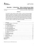
9 (2)Global Automotive Declarable Substance List, see All products comply with the IEC 62474, Material Declaration for Products of and for the Electrotechnical Industry. CEFIC (European Chemical Industry Council), EECA (European Electronic Component Manufacturers Association), EICTA (European trade organization representing the information and communications technology and consumer electronics), see (3)Other cleaning solvents with aggressive chemicals should be evaluated in actual cleaning process for their Beyschlag Revision: 19-Jan-164 Document Number: 28736 For technical questions, contact: DOCUMENT IS SUBJECT TO CHANGE WITHOUT NOTICE. THE PRODUCTS DESCRIBED HEREIN AND THIS DOCUMENTARE SUBJECT TO SPECIFIC DISCLAIMERS, SET FORTH AT DESCRIPTIONC1001500- Temperatureamb Power DissipationPCBB 0207 Derating - Power Temperatureamb Power DissipationP CCBB 020750 Derating - Standard OperationCBB 0207020604080 KTemperature RiseCBB Beyschlag Revision: 19-Jan-165 Document Number: 28736 For technical questions, contact: DOCUMENT IS SUBJECT TO CHANGE WITHOUT NOTICE.
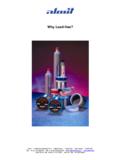
10 THE PRODUCTS DESCRIBED HEREIN AND THIS DOCUMENTARE SUBJECT TO SPECIFIC DISCLAIMERS, SET FORTH AT DESCRIPTION100 s 1 ms10 ms11 s 10 s s100 ms10100 Pulse DurationtiPulse 0207 Maximum Pulse load , single Pulse ; for permissible resistance change equivalent to 8000 h Pulse100 s1 ms10 ms11 s 10 s s100 ms10100 Pulse DurationtiContinuous Pulse 0207 Maximum Pulse load , continuous pulses; for permissible resistance change equivalent to 8000 h Pulse100 s1 ms10 ms1 s 10 s 1 kV100 V10 s100 msPulse DurationtiPulse 0207 Maximum Pulse voltage, single and continuous pulses; for permissible resistance change equivalent to 8000 h VoltageCBB Beyschlag Revision: 19-Jan-166 Document Number: 28736 For technical questions, contact: DOCUMENT IS SUBJECT TO CHANGE WITHOUT NOTICE. THE PRODUCTS DESCRIBED HEREIN AND THIS DOCUMENTARE SUBJECT TO SPECIFIC DISCLAIMERS, SET FORTH AT DESCRIPTION100 V1 kV10 V10 kV100 1 k 10 k 100 k 10 10 M Resistance ValueR1 M CBB 0207 Test Voltage sPulse load rating in accordance with IEC 60 115-1, ; s/50 s; 5 pulses at 12 s intervals;for permissible resistance change %.