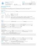
Transcription of Pressure Distribution, Orifice, Pipe & Pump Sizing
1 This worksheet is for use in Alberta to: size the orifices in distribution lateral pipes, size effluent delivery piping, Minimum Pressure at the orifice:3/16" or less orifice = 5 ft. Minimum - (1), (p 38)larger than 3/16" orifice = 2 ft. Minimum - (1) (p 38)Note: larger sizes are less likely to of distribution LateralFrom system design drawingsSelect a spacing of orifices to attain even distribution over the treatment area:P3bNumber of Laterals =Step 1) Select the Pressure head to be maintained at the orifices:Orifice Diameter selectedSpacing of Orifices selected for designP3aResulting number of orifices per lateralDesign Pressure at lateral orifices Pressure distribution , Orifice, Pipe & Pump SizingThis design worksheet was developed by Alberta Municipal Affairs and Alberta Onsite Wastewater Management completed installation is to comply with Alberta Private Sewage Standard of Practice worksheet does NOT consider all of the mandatory requirements of the is intended for use by persons having training in the private sewage only Imperial units of measurement throughout (feet, inches, Imperial gallons, ).
2 From P3aMaximum spacings are determined for :* 5 ft. Primary treated effluent: (1)(e) p. 37* 3 ft. Secondary treated effluent: & (c) (pp 77 & 38)* 3 ft. On sandy textured soils: (p. 77)=Minimum size: (1)(e) p. 37 P2 and to calculate the required capacity and Pressure head capability of the effluent pump. It can be used for: calculating delivery of effluent to laterals in disposal fields, mounds and sand filters. Note: Page numbers refer to the Private Sewage Systems Standard of Practice 3) Select the spacing of orifices and determine the number of orifices to be installed in distribution laterals:P1 Step 2) Select the size of orifice in the laterals:1/8"Note: worksheet will not provide an adequate design if laterals are at different elevations.
3 Differing elevations will result in a different Pressure head and volume of discharge at the orifices in each lateral. Additional considerations must be made for laterals at differing elevations. ft. in. ft. ft. XTotal Number of Orifices All LateralsIf laterals are of differing lengths, calculate each separately and add the number of orifices Feb 14, 2016HO 109 - 02at Head Pressure Selectedinch- NPSUse Tables to (pp 124 - 127) to aid in decision. A larger pipe will reduce Pressure size selectedType of pipe used for effluent delivery lineFrom P3b Equivalent Length of All FittingsXEnter the system design information into the 3 boxes below. If distribution laterals are of differing lengths, each lateral must be considered Number of Orifices in all lateralsLength of distribution LateralP6 From P2 Gal/min for each OrificeStep 7) Calculate the equivalent length of pipe for Pressure loss due to fittings:Total flow from all lateral orificesFrom Table (pp 122 & 123)Orifice DiameterFor Pressure LossP7 Step 4) Determine the minumum pipe size of the distribution laterals:Step 5) Determine the total flow from all orifices:Imp.
4 Gal system Design Drawings=Imp. gal /min. ft. total from Worksheet "A" on last page ( ) of this Pressure distribution WorksheetStep 6) Select the type and size of effluent delivery pipe:Choose a friction loss from Tables to in between the bolded lines to ensure a flow velocity between 2 to 5 feet per second. The pipe size selcted will affect the amount of friction loss the pump must overcome to deliver Table From P3a Total Orifices Each LateralSize of distribution Lateral Pipe Table (pp 118 - 121) when applying the information entered in this step to determine the minimum size of the distribution lateral Feb 14, 2016HO 109 - 02 From P8 Step 10) Calculate the total Pressure head required at pump:Measure from lowest effluentlevel in tank to elevation of Pressure Loss Allowed if AppliedStep 8) Calculate the equivalent length of pipe from pump to the farthest end of header of distribution laterals for Pressure loss.
5 Equivalent fitting length from Length of Pipe for Friction LossEquivalent Length of Fittings(ft) ft. P8=+Length of Pipe for Friction Loss (ft)Length of Piping(ft)Don't forget to divide the length by 100 feet to match the factors in the 9) Calculate the Pressure head loss in delivery pipe including fittings:Delivery Piping Pressure Head LossUsed to determine total Pressure head loss due to friction loss in piping. ft. P9 Use Tables On pp 124 - 127 using flow volume from P5. ft. P9 P1 Lift distance of effluent from effluent level in tank to orificesFriction Loss per 100 feet of pipeLength from pump to farthest end of distribution header supplying laterals.
6 Loss allowed if an inline filter is used in Pressure piping+Add 1 ft to allow for Pressure loss along the distribution lateralP10+Divide by 100 minimum Pressure head pump must provide at Imp. gal/min required to supply orificesx+Design Pressure at orifices ft. piping Pressure loss=+1 Revised Feb 14, 2016HO 109 - 02 Step 12) Details of the pump specifications required:Imp. gal /minP11 Step 13) Consider the pumping demands of the system . If they are considered excessive, redesign the Pressure distribution system and recalculate the pump Imp. Gallons per Minute from the pumpRequired Flow Rate (Imp. gal/min)Required Pressure Head (ft)From P11 From P10 Use Pressure head from P10 to find flow from Extended Table @Size of Drain Back OrificeImp.
7 Gal (P11) multiplied by = gallons gal /minDetermine flow using Head Pressure at Drain Back OrificeImp. gal /minRequired Flow Rate (US gal/min)Flow from all lateral orificesStep 11) Select the size of the drain back orifice if used and determine the flow from the drain back orifice. Then calculate total flow requirement for pump:Select the appropriate pump by reviewing the pump curve of available pumps. Select a pump that exceeds the requirments set out in this step by approximately 10% considering both Pressure head and P5+=Revised Feb 14, 2016HO 109 - 02 Determine the equivalent length of pipe to allow for friction loss due to fittings in the piping system :Total+++++(M/F Threaded Adaptors)(Enter this total, Box P7) Worksheet "Appendix A" Determine Equivalent Length of Pipe due to fittings in piping (TOB)Male Iron pipe Adaptors (MIP)Tee-on-Runs (TOR)Gate and Ball Valves45 ElbowsFriction loss as per Table or 6 (p.
8 128)Number of Fittings90 ElbowsXX==X=X=X=X=Total Equivalent Length of pipe to allow for fittings in piping systemRevised Feb 14, 2016HO 109 - 02