Transcription of Duct Static Pressure Control - Viking Controls
1 Metasys Network Technical Manual 636 App. Notes: All Electric DDC SectionApplication NoteIssue Date 0393 1993 Johnson Controls , No. Application Note describes how to use Direct Digital Control (DDC)to implement duct Static Pressure Application Note includes:lSequence of OperationlSystem SchematiclComponent ChoiceslDesign ConsiderationsThis Application Note assumes you have a working knowledge of:lHVAC Control theorylHVAC controllers, including Metasys NCM, DCM, Companion ,and application specific controllerslstatic Pressure sensorsDuct Static Pressure ControlIntroductionAssumptions2 App. Notes: All Electric DDC duct Static Pressure ControlThe controller uses a Static Pressure sensor located in the supply duct (at the end of the longest run) to modulate the supply fan to Control ductstatic a call for full Pressure , the fan runs at full speed. As duct staticpressure increases, the supply fan speed optional discharge air Static high limit reduces the fan speed ifdischarge Static Pressure increases above its 1: duct Static Pressure ControlTable 1: Fan SpeedFAN SPEED CONTROLLER INPUTDCMAHU4 to 20 mAXX0 to 10 VDCX** Use a 500 ohm resistor to provide 2 to 10 2: Discharge Static -Panel MountedDISCHARGE Static HIGH LIMIT (PANEL MOUNTED)DCMAHUFM-IDP100-0, 0 to in.
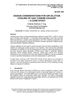
2 (0 to 2490 Pa)XFM-IDP250-0, 0 to in. (0 to 6227 Pa)XFM-IDP050-0, 0 to in. (0 to 1245 Pa)XSequence ofOperationSystem SchematicOutside AirExhaustFan SpeedControlDischarge StaticSensor or High LimitReturnDischargeDuct StaticPressure SensorH LH LDDC_APP3 ComponentChoicesApp. Notes: All Electric DDC duct Static Pressure Control 3 Table 3: Discharge Static -Remote MountedDISCHARGE Static HIGH LIMIT (REMOTE MOUNTED)DCMAHUDPT-2640-7, 0 to in. (0 to 2490 Pa), 0 to 5 VDCXDPT-2641-7, 0 to in. (0 to 2490 Pa), 4 to 20 mAXDPT-2640-8, 0 to in. (0 to 6227 Pa), 0 to 5 VDCXDPT-2641-8, 0 to in. (0 to 6227 Pa), 4 to 20 mAXDPT-2640-6, 0 to in. (0 to 1245 Pa), 0 to 5 VDCXDPT-2641-6, 0 to in. (0 to 1245 Pa), 4 to 20 mAXTable 4: Dual Static -Panel MountedDUCT Static Pressure SENSOR (PANEL MOUNTED)DCMAHUFM-IDP030-0, 0 to in. (0 to 747 Pa)XXFM-IDP050-0, 0 to in. (0 to 1245 Pa)XXFM-IDP010-0, 0 to in. (0 to 249 Pa)XXFM-IDPB025-0, to in.
3 ( Pa to Pa)XXFM-IDPB050-0, to in. (-1245 Pa to 1245 Pa)XXFM-IDPB010-0, to in. (-249 to 249 Pa)XXTable 5: Dual Static -Remote MountedDUCT Static Pressure SENSOR (REMOTE MOUNTED)DCMAHUDPT-2640-5, 0 to in. (0 to 623 Pa), 0 to 5 VDCXXDPT-2641-5, 0 to in. (0 to 623 Pa), 4 to 20 mAXXDPT-2640-6, 0 to in. (0 to 1245 Pa), 0 to 5 VDCXXDPT-2641-6, 0 to in. (0 to 1245 Pa), 4 to 20 mAXXDPT-2640-4, 0 to in. (0 to 249 Pa), 0 to 5 VDCXXDPT-2641-4, 0 to in. (0 to 249 Pa), 4 to 20 mAXXDPT-2640-25, to in. ( Pa to Pa), 0 to 5 VDCXXDPT-2641-25, to in. ( Pa to Pa), 4 to 20 mAXXDPT-2640-26, to in. (-1245 Pa to 1245 Pa), 0 to 5 VDCXXDPT-2641-26, to in. (-1245 Pa to 1245 Pa), 4 to 20 mAXXDPT-2640-24, to in. (-249 to 249 Pa), 0 to 5 VDCXXDPT-2641-24, to in. (-249 to 249 Pa), 4 to 20 mAXX4 App. Notes: All Electric DDC duct Static Pressure ControlThis section lists things to consider when choosing the DDC componentsfor this application.
4 For specifics on ordering and wiring, refer to theappropriate documentation for each interface supplied with the motor speed controller must provide either0-10 VDC or 4-20 mA interface to communicate with the HVAC controller. The input for the motor speed controller must have it does not provide isolation and you are controlling with a DCM, use anFM-OAI101-0 to provide isolation. If you are using an AS-AHU101, themotor speed controller has to provide the isolation if more than one motorspeed controller will be controlled by this AHU. Contact the supplier of themotor speed controller to determine if their input has provide a modulating high limit, discharge Static high limit must bedone through a Digital Control Module. The AHU controller doesn tprovide for this type of Control . The controller can also provide 2-positionhigh limit, as well. If external limits are required, a (manual reset)differential Pressure switch is required. Wire the Pressure switch into thefan starter circuit to stop the fan when its setpoint is the Static Pressure sensor at the panel.
5 Sensors located above aceiling tend to get lost and forgotten. Run two 1/4 inch sensing lines(High and Low) to the sensing a Static Pressure sensor that allows the HVAC controller to operatein the upper half of the sensor s normal operating range. The normalrange for duct Static Pressure is from in. to in. water to Volume II of the Metasys Network Technical Manual, FAN 636for complete details on IDP Function to Engineering Report 447, Section 1, FAN 351, for furtherinformation on Static Pressure sensing locations and Control AS-AHU100 can accomplish the Control sequence in most you have an extremely complex unit with humidity, building staticpressure, and discharge air Control as well, use an NU-DCM101 controllerin conjunction with an Network Configuration Guide in the Metasys Network Sales ResourceManual, FAN 635 discusses choosing an HVAC SpeedControllerDischarge StaticHigh LimitDuct Static PressureSensorHVAC ControllerControls GroupFAN 636507 E.
6 Michigan StreetMetasys Network Technical Box 423 Printed in , WI 53201