Transcription of COMPOSITE LANDING GEAR COMPONENTS FOR …
1 24TH INTERNATIONAL CONGRESS OF THE AERONAUTICAL SCIENCES1 AbstractComposites are being used increasingly forstructural COMPONENTS for aircraft and spaceapplications because of their superior specificstrength and stiffness properties in comparisonaluminum and steel. The weight savings thatwere realized by applying composites used to beone of the main drivers to apply these , nowadays a reduction in fabricationcost is becoming important as well. Theobjective therefore is to combine new costeffective fabrication methods with lightweightstructural concepts in order bring theexploitation of COMPOSITE materials to a to now, the autoclave process is thestandard fabrication technique to producecomposite COMPONENTS for the aerospaceindustry.
2 Recent developments show theevolution of new cost efficient fabricationtechniques and of COMPOSITE materials for thesenew techniques. One of these (for the aerospace)new fabrication methods is Resin TransferMoulding (RTM). The RTM fabrication conceptis based on the injection of resin into a mouldcavity containing dry fibers (preform). Duringthe injection process, air in the mould is beingreplaced by resin and the fibers are RTM tooling can be complex andexpensive, RTM has several advantagescompared to autoclave processing. One of theseadvantages is that thick complex shapedcomponents can be made that would be verycumbersome or even impossible to make byautoclave processing.
3 This means that designersnow can design COMPOSITE COMPONENTS asreplacement of COMPONENTS made with the framework of several technologyprograms the Structures TechnologyDepartment as part of the Aerospace Vehiclesdivision of NLR developed several compositelanding gear COMPONENTS for a large militaryhelicopter and a fighter aircraft. These programswere carried out in close collaboration with thelanding gear manufacturer SP aerospace andvehicle systems. The targets of the programswere to achieve not only weight reductions of20% but also to reduce the manufacturing costsby 15% and to achieve a reduction in different LANDING gear componentswere fabricated successfully by RTM andtested.
4 All tested LANDING gear componentsfailed beyond their required failure load program targets were present paper will present an overviewof the design concepts of these compositelanding gear COMPONENTS . The RTM toolingconcepts and the RTM manufacturing set-upswill be described and a brief overview of thetest results will be IntroductionComposites are being increasingly used forstructural COMPONENTS for aircraft and spaceapplications because of their superior specificstrength and stiffness properties in comparisonaluminum and steel. The weight savings thatwere realized by applying composites used to beone of the main drivers to apply these LANDING gear COMPONENTS FORAEROSPACE ThuisNational Aerospace Laboratory NLRK eywords: Composites, Resin Transfer Moulding, LANDING Thuis National Aerospace Laboratory NLR2 However, nowadays a reduction in fabricationcost is becoming important as well.
5 Theobjective therefore is to combine new costeffective fabrication methods with lightweightstructural concepts in order bring theexploitation of COMPOSITE materials to a to now, the autoclave process is thestandard fabrication technique to producecomposite COMPONENTS for the aerospaceindustry. Recent developments show theevolution of new cost efficient fabricationtechniques and of COMPOSITE materials for thesenew techniques. One of these (for the aerospace)new fabrication methods is Resin TransferMoulding (RTM). The RTM fabrication conceptis based on the injection of resin into a mouldcavity containing dry fibers (preform).
6 Duringthe injection process, air in the mould is beingreplaced by resin and the fibers are RTM tooling can be complex andexpensive, RTM has several advantagescompared to autoclave processing: Matched die tooling concepts can be used,assuring tight outer dimensional tolerances,hence reducing the amount of shimmingduring assembly Net-shaped or nearly net-shapedcomponents can be made, hence reducingthe amount of trimming after curing thecomposite component Complex shaped thick COMPONENTS can bemade that would be very cumbersome oreven impossible to produce by RTM fabrication concept makes itpossible for designers to replace metal forgingby COMPOSITE COMPONENTS .
7 This opens the doorfor designers to develop COMPOSITE LANDING gearcomponents. In order to demonstrate thefeasibility of COMPOSITE materials in landinggear applications, NLR carried out severaltechnology programs. These programs werecarried out in close collaboration with thelanding gear manufacturer SP aerospace andvehicle systems. The main targets of theseprograms were to realize a cost reduction of15% and a weight reduction of 20% byreplacing metal LANDING gear COMPONENTS bycomposite present paper presents thedevelopment of two different LANDING gearelements: a drag brace for a fighter aircraft anda trailing arm for a helicopter.
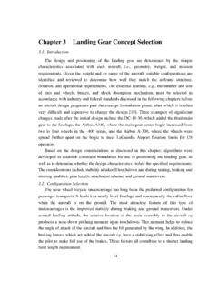
8 The designconcepts will be described followed by adescription of the manufacturing process. Mostof the LANDING gear COMPONENTS were tested. Thepaper will present a brief overview of these testprograms followed with a presentation of thetest F-16 Drag brace developmentIn order to demonstrate the feasibility ofhighly loaded COMPOSITE LANDING gearcomponents a technology demonstrator had tobe selected. After a survey, the lower drag braceof the main LANDING gear of a fighter wasselected. Figure 1 presents an overview of the F-16 main LANDING gear and the location of thelower drag 1: F-16 main LANDING gear and positionof the lower drag component was selected since thelower drag brace is one of the main loadcarrying elements of the LANDING gear and isloaded both in tension and compression duringtake-off and LANDING operations.
9 Therefore thetechnological value of this component was reason for selecting this component3 COMPOSITE LANDING gear COMPONENTS FOR AEROSPACE APPLICATIONSwas the fact that SP aerospace and vehiclesystems fabricates the metal (high strengthsteel) drag brace in series production. Thismeans that within this program a goodcomparison in performance, weight and costsbetween the COMPOSITE and the metal drag bracecould be COMPOSITE drag brace had to meet alarge number of requirements. The mostimportant were: The lower drag brace had to fit in the mainlanding gear of an F-16 fighter The maximum weight was limited to kg(80% of the weight of the steel drag brace) Impact damages up to 86 Joule should notlead to a reduction in strength The drag brace should be able to operate at700C and 85% relative humidity The chemical resistance of the compositematerial used should be present metal (high strength steel)lower drag brace is configured as an I-shapedbeam.
10 For the conceptual design of thecomposite drag brace the box girder conceptwas selected. This concept was selected since abox girder has a limited number of free edgesthat are sensitive to impact damages, henceincreasing the damage tolerance of the dragbrace. The COMPOSITE drag brace was configuredwith three lugs: two to enable the rotation of thecomponent during take-off and LANDING of theaircraft and one for connecting a locking middle of the drag brace was tapered inorder to meet the interface requirements of themain LANDING gear . Since at the moment theconceptual design was made no designallowable of the materials used were at hand,the conceptual design was based on assumeddesign used and material propertiesFor fiber reinforcements Non CrimpedFabrics (NCF)