Transcription of The Crystal Radio - American Radio Relay League
1 The Crystal RadioQST December 1997, pp. 56-57 Copyright 1997 by the American Radio Relay League , Inc. All rights reservedE56 December 1997ven a casual auditor of the amateur bands will con-clude that the hobby is largely populated by wizenedold geezers and I m one of them. This is a sad situ-ation because most of us entered Amateur Radio as ham Radio is to continue for generations to come, we must getyoungsters interested in Radio communication while they re stillin grammar school and still capable of wonder. We need to reachthem while they are still asking questions about everyday matters(that all too often go unanswered) such as, Why does it get lightin here when I push this thing? Reaching today s kids won t be easy. With the Internet, cellu-lar telephones and other forms of global communication common-place in their lives, the true magic of Radio lies buried beneath thetechnology.
2 We must strip away layers upon layers of complicatedhardware and reveal Radio in its purest form. The perfect tool toachieve this goal is the lowly Crystal the curiosity you ll inspire when you demonstrate aradio that has no obvious power source whatsoever! The simplecrystal receiver described in this article works surprisingly s selective and produces robust headphone volume. I ve beenable to tune several local AM broadcast stations with ease. Best ofall, it s inexpensive, uses readily available parts, and can be builtby a youngster (with a little guidance). Of course, adults will lovethis little receiver, is a fascinating resurgence of interest in Crystal hams normally accustomed to owning rigs with four-digitprice tags are rediscovering the joys of simple, powerless recep-tion. To get a taste of what is going on, pick up a copy of CrystalSet Projects from the Xtal Set Society, Box 3026, St Louis, MO63130; tel 314-725-1172, or visit their Web site at (The book was reviewed in theAugust, 1997 QST, page 102.)
3 About the CircuitThe circuit shown in Figure 1 was developed in the early 30sby Elmer G. Osterhoudt. Selectivity problems plagued most crys-tal sets of the day due to the proliferation of broadcast devised a solution. He determined that poor Crystal receiverselectivity was caused by the headphones swamping the tunedcircuit and lowering its Q. The net result was an inability to sepa-rate individual signals. Elmer improved selectivity considerablyby connecting the detector near the cold (ground) end of the tunedcircuit to minimize the C2 is used to match the antenna system, and C3 is themain tuning capacitor. Absent from this circuit is the finicky ga-lena-and-catwisker detector. It has been supplanted by a 1N34germanium diode that is connected near the grounded end of thetuned circuit that includes coil L1. C1 is an RF bypass must use high-impedance headphones (2000 or greater)with Crystal receivers.
4 If you attempt to use common 8- head-phones, you ll have very disappointing results. You ll find high-impedance headphones at hamfest flea markets, but if you re notBy Dave Evison, W7 DEThe Crystal RadioWhat s old is new again!C1 1000 pF mica or disc ceramic trimmer ( Radio Shack272-123)C2 40 to 500 pF trimmer capacitor (Antique ElectronicSupply CV-263)C3 365 pF variable capacitor (Antique Electronic SupplyCV-231)D1 1N34 germanium diode ( Radio Shack 276-1123)J1 1/4-inch, 2-conductor headphone jack ( Radio Shack274-252)L1 35 feet of 22-gauge enamel wire. See text. ( Radio Shack278-1345)Fahnestock clips (Antique Electronic Supply SH-11-4034)2000- headphones (Antique Electronic Supply PA-466)Figure 1 Schematicdiagram of the crystalreceiver. Parts areavailable from RadioShack or AntiqueElectronic Supply(6221 South MapleAve, Tempe, AZ 85283;tel 602-820-5411) to the hunt, you can buy them from Antique Electronic Supply(see Figure 1).
5 The Importance of a Good Antenna SystemSince the Crystal receiver depends completely on the energyfrom the transmitted signal, you need to gather as much signal outof the air as possible! Remember that this receiver is designed totune the AM broadcast band. A half-wavelength dipole cut forabout 1 MHz would be ideal, but few of us own enough real estateto accommodate a 500-foot long antenna. The practical solution isto simply use an end-fed wire about 100 feet in length. You ll alsoneed to provide a connection to an Earth ground (a cold-water pipemay suffice). With the proper antenna system, you should be ableto receive most of the AM stations in your area. If you live in arural location without an AM broadcaster nearby (within about50 miles), try using even more antenna wire. Just string it overtrees, bushes, or any other can build a Crystal receiver into almost anything. I usedplastic electrical outlet boxes.
6 They re available at home centersand hardware stores. They are attractive, rugged and even serve as forms for winding the coil. I made the frontpanel of my box from a piece of copper-clad PC board. You cancut this material into the proper shape using a hacksaw, and it iseasily drilled for mounting C3, a miniature variable capacitor salvaged from an oldAM-only Radio will work, but a single-section air variable is bet-ter. If you don t have these capacitors in your junk box, don tdespair. You can order one from Antique Electronic is wound on the outside rear portion of the enclosure andconsists of 32 turns of 22-gauge enamel-covered wire. The coil istapped nine turns from the grounded end. The tap is made bytightly twisting about 1 inch of the magnet wire and scraping offthe enamel insulation. You can secure the windings to the enclo-sure with transparent plastic antenna trimmer capacitor (C1) and the Fahnestock clipsfor the antenna and ground connections are mounted on the rear ofthe enclosure.
7 The tuning capacitor, phone jack and detector aremounted on the front panel. Interconnecting wires are fed throughholes in the enclosure and soldered to the trimmer capacitor,ground and cold AdjustmentsConnect the antenna, ground and headphones. Tighten theantenna trimmer capacitor C2. Slowly adjust C3 to tune in thestations. Note the number of stations and log their call letters andfrequencies. Readjust C1 to provide the best trade-off betweenvolume and selectivity. If you re using your Crystal Radio near aparticularly strong broadcast station, removing the ground con-nections will often improve selectivity (with some reduction involume).Use Your Radio as a Teaching Tool!You can use your Crystal Radio to teach a number of importantconcepts. For example:153 Park AvePalo Alto, CA 94306e-mail Applying the right hand rule, the coil for thetuned circuit can be used to explain how a magnetic field is devel-oped by electron flow through a conductor, and how the magneticfield is increased by forming the conductor into a : Varying capacitance may be illustrated by sim-ply observing how the total area increases as the rotor plates meshwith the stator plates.
8 The compression trimmer capacitor (C1)illustrates the function of a dielectric other than air. It also showshow the capacitance can be varied by changing the separationbetween the , modulation and detection: You can teach theseconcepts by inviting your student to tune in a station while youdisplay the modulated RF on an oscilloscope! Move the scopeprobe from one side of diode D1 to the other to illustrate before and after. Magnetism and transduction: High-impedance headphones areideal instructional aids to demonstrate these ideas. Disassemble apair of headphones and show your students what s inside. Touchthe permanent magnet with a screwdriver so they can see that it isindeed magnetic. Explain how the detected signal flows throughthe tiny headphone coil, creating a magnetic field that adds orsubtracts from the field produced by the permanent magnet. Thiscauses the metal diaphragm to vibrate, creating sound!
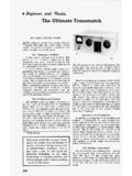
9 Whatbegan as electrical energy has become mechanical energy the years, the simple Crystal Radio has spawnedtens of thousands of Radio amateurs, engineers and electronichobbyists. And despite the antiquity of its design, it is still aneffective tool for recruitment and instruction. A Crystal Radio is adelightful device, and the perfect way to introduce the wonder ofradio to a young mind or rekindle it in your own!Plastic electrical outlet boxes make terrific enclosures. Notethat I ve mounted the main tuning capacitor, C3, and theheadphone jack on the front using copper-clad PC rear view of the Crystal Radio enclosure. You can easilysee the windings of coil L1 held in place with 199757