Transcription of A Simple yet Precise Function Generator for the …
1 Rubens Fernandes, VK5FE. 16 Tilly St, Mt Barker, SA 5251, Australia, A Simple yet Precise Function Generator for the Experimenter Clean sine waves from Hz to 3 MHz, triangular waves up to 300 kHz, output from 110 dBm up to +10 dBm on 50 , flat response, square waves, Precise level and frequency adjustment and much more! Many times I've missed having a general purpose Generator on my workbench for testing digital circuits, audio amplifiers, filters in the audio range, keyer input of rigs, switching power supply loads on/off to check their performance when transmitting code and so on. On those occasions I. normally had to quickly create Simple circuits to overcome the situation until when, not long ago, I was testing a frequency counter on lower frequencies and needed a Precise low-frequency Generator . 1 The solution was to look among my friends for such an instrument, but I knew that wasn't a viable approach for the long term.
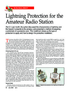
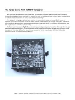
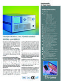
2 That's when I promised myself that I would try to design my own Simple , but reliable, Generator as soon as possible. The device that is presented here fulfilled my expectations, and some of the design ideas eventually can be useful to other experi menters as they build their own instruments. There are also many hams who Photo 1 The assembled Function Generator . enjoy assembling and testing quality audio amplifiers. Again, due to its spectral purity and flatness, a good general purpose Generator could be helpful. For those Architecture Generator . There is no provision for dc offset, interested in assembling the circuit shown The block diagram is shown in Figure 1 adjustable rise and fall times or other fancy here, fully functional firmware (a hex file) is and the assembled unit in Photo 1. There are waveforms. Concerning the triangular available on the QEX web page at four boards: Main Board, that includes the waves, it's a bonus the DDS chip can org/qexfiles.
3 Look for file 5 13_Fernandes. time base, processor and DDS (Direct naturally output this waveform , but it had to zip. I don't recommend this project for Digital Synthesis) chip, the Reconstruction be limited to 300 kHz as it is rich in odd beginners as it uses SMD (Surface Mount Filter Board, the Amplifiers Board, with the harmonics and the reconstruction filter has a Devices) extensively one of them an final amplifiers and level adjustments and cut-off frequency of about 3 MSOP (Mini Small Outline Package) with the Power Supply Board, which generates all The auxiliary connector will output a terminal spacing of mm ( inches). the dc levels needed by the circuits. 50 s pulse each time a new sweep starts The Generator is capable of outputting (when in sweep mode), that can be used for fixed or swept sine waves, square waves and synchronization purposes.
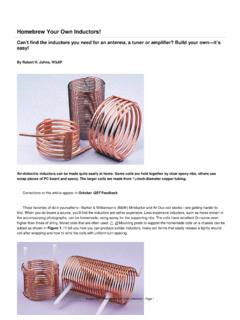
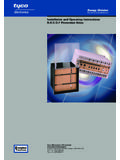
4 The pulse 1. Notes appear on page 15. triangular waves. It is also a Simple pulse Generator output is available at this same QEX May/June 2013 3. connector and has fixed amplitude of 5 Vp CFPS-39IB is a 50 ppm time base and, Main Board only. Although very useful in the stage as it is working together with the AD9833, gave See Figure 2. I have chosen the AD9833, now, eventually this Generator will be nice results, although not being expensive a not-so-new waveform Generator for three upgraded to generate adjustable pulse levels, parts, as you will see in other topics. Notice reasons: first due to its low pin-count, second more Precise pulse widths and better rise and that 50 ppm is the overall stability, considering because I had some units bought for half the fall times. the 40 to +85 C temperature range, the regular price from a major vendor and, The 16 2 display has two modes; in the plus/minus 10% of supply voltage excursion finally, it has the specifications I needed.
5 First one, the upper line will show the and load variations. As load and supply are As we know, the quality of the output of a frequency and the second line the amplitude. constant and keeping the temperature range DDS chip depends heavily on the quality of From now on this mode will be called inside let's say, 10 C, the stability will be its time base. On the other hand, the quality normal display. The second is the menu very good. Nevertheless, the wake-up of the output of a time base chip is dependent mode, and for each menu option an adequate frequency of those time bases can vary and on its power supply. The SPX5205M5L33 is display disposition will be used. are not so accurate in respect to its nominal a low noise V regulator and the Figure 1 Block diagram. 4 QEX May/June 2013. Figure 2 Main board schematic. QEX May/June 2013. 5. frequency.
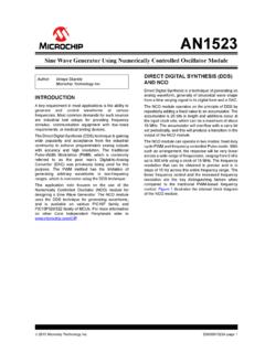
6 This creates an accuracy problem as the frequency output by the DDS is a fraction of the time base frequency. The solution was to include a calibration procedure to correct the reference frequency used in the calculations that have to be done each time the frequency in the chip is changed. The inverter/Schmidt trigger was used mainly as a level adapter, as the time base uses a V dc power supply and the processor and DDS are working with 5 V dc. The two components named NS are noise suppressors, used just as a precaution. The display is a conventional 16 2 unit, white- over-blue characters (less power consump . tion). For simplicity I avoided the use of a variable dc level for the backlight LEDs, using instead two diodes to reduce the voltage. With the same philosophy, the contrast adjustment is made with two fixed resistors. In fact, just the k resistor to Photo 2 Main Board, component side.
7 Ground should do the job. The external encoder is connected through CN2 and its switch via CN3. The AD8055 is a 300 MHz voltage feedback amplifier connected to have a voltage gain of about 4 and is also responsible for the 0 V dc level adjustment. The main board implementation can be seen in Photos 2 and 3. Analog and digital grounds are separated and are connected in just one point of the printed circuit board. Reconstruction Filter Board See Figure 3. Although being a Simple low pass filter, this circuit plays a very Figure 3 Reconstruction filter board schematic. Figure 4 Aliases (Courtesy of Analog Devices). 6 QEX May/June 2013. important role in the Generator . A DDS chip association of a 10 k linear potentiometer gang connected to the +5 V supply and the like this one builds the waveform using and the attenuator; the potentiometer range is center pin is connected to one of the analog to discrete voltage samples whose amplitudes a bit more than 20 dB, overlapped with each digital converter (ADC) inputs of the vary according to the shape you want (in this section of the attenuator.)
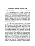
8 This association microprocessor. In other words, the processor case, a sinusoid). It it is expected that the permits the control of the output level keeps track of the position of the wiper and corresponding analog waveform will be continuously from 70 dBm to +10 dBm. then knows how much the signal is being reconstructed ahead, which is exactly the For sensing the level of the sine and attenuated in the other gang. Although Function of this filter hence the name. triangular waves, a different approach was seeming very nice in theory, this procedure Theoretically the chip can output signals up used. The 10 k potentiometer has a second has a drawback: ordinary linear to half the frequency of the time base, according to the sampling theorem. However, one fact of life is that the process of generating the waveform also generates aliases. In other words, it adds distortions to the desired waveform .
9 Aliases are images of the fundamental frequency that are repeated around the clock frequency and its harmonics;. this is shown in Figure 4, borrowed from the Analog Devices Addi . tionally, things are a bit worse due to the fact that there is also an inevitable clock feed through, meaning that some amount of the clock frequency (and harmonics) is also present at the output (not shown in the figure). Other sub-products can also appear in the output. The filter had to be designed and implemented taking into consideration the bandwidth of the amplifiers and the desired quality of the signal in the entire range. The filter had to respond far beyond the cut-off Photo 3 Main Board, solder side. frequency, blocking all unwanted signals. The input and output impedance is 50 and its shape is shown in Figure 5. The S21. parameter line is the gain magnitude (or the negative value of the insertion loss), and the S11 parameter line is the reflection coefficient magnitude (or the negative value of the return loss).
10 Notice that there is a slight decay in the magnitude before reaching the knee, due to filter losses. Photos 4 and 5 show the assembled board. Amplifiers Board As can be seen in Figure 6, the input Photo 4 Reconstruction Filter, component side. signal coming from the reconstruction filter is split in two and routed to two amplifier chains. In the upper section the sinusoidal and triangular waveforms are first amplified by the AD8055 and then directed to an attenuator having three sections of 20 dB. The first relay was included to provide a way of disconnecting the Generator output, but keeping the 50 output impedance. The 500 potentiometer adjusts the gain of the stage and the network formed by the k . resistor and 47 pF capacitor connected to Pin 4 compensates the filter losses mentioned before, actuating in the feedback loop of the operational amplifier.