Transcription of Lightning Protection for the Amateur Radio …
1 48 july 2002By Ron Block, KB2 UYTBy Ron Block, KB2 UYTBy Ron Block, KB2 UYTBy Ron Block, KB2 UYTBy Ron Block, KB2 UYTThe process described in Part 1 of identifying the equip-ment to be protected can be applied to any item or setof electronic equipment. With some adjustment, it canbe applied to tower-top electronics such as preamps or poweramplifiers, to a computer installation in another room, a TV ora stereo system. The principle is the same: identify all of theelectrically and proximally connected equipment, identify allof the I/O (input/output) lines, add protectors and ground. Thetheory is easy; it s the implementation that can be Each I/O LineLet s examine each of the I/O lines identified in the box-level schematic, dividing them into broad categories for dis-cussion.
2 Each I/O line represents a potential source or sink(ground) for Lightning strike energy, either directly fromMother Nature or indirectly via a connecting wire or arc. Wemust provide a protector that is physically and electrically ap-propriate for the type of I/O line we are protecting. The pro-tector has a relatively simple job to do short circuit whenthreatened (over voltage). While this may seem like a rela-tively simple thing to do, it is surprisingly difficult to accom-plish without first sharing much of the strike energy with yourequipment. This is especially important for receivers with sen-sitive FET front-end stages and electronic interfaces (RS-232,422, and so on) where the maximum tolerable interface volt-age is just a few volts above the operating best I/O line protectors are connected in series betweenthe surge and the circuit they are intended to protect.
3 Seriesprotectors, by design, have the capability to limit the amountof Lightning strike energy your equipment will receive. The better manufacturers will specify the maximum amount of let-through energy your equipment will receive during astrike. It is normally specified as a quantity of energy in themilli- or microjoule range. When choosing a protector, selectthe one with the least let-through energy that meets all of therequirements for the CableThe first category of protector we will examine is the co-axial cable line protector. Coaxial protectors are unique in thatLightning Protection for theAmateur Radio StationPart 2 Last month, the author discussed the characteristics of Lightning andthe hazard it presents to the Amateur , and presented a method of preparinga schematic of a Protection plan.
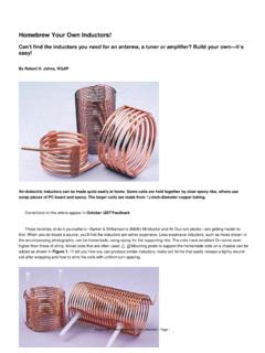
4 This installment shows us the type ofprotection to apply and how to design the protective should not add to system SWR or signal loss, and at thesame time they need to operate over a very broad frequencyrange at both receive and transmit power coax line leaving the circle around the protected equip-ment must have an appropriate coaxial protector. As we willdiscuss later, the coax protector along with all of the other I/Oprotectors must be mounted on a common plate (or panel) andconnected to an external ground typical PolyPhaser protectors for Amateur Radio usebelow 1 GHz are shown in Figure 7. While both of these protec-tors are shown with UHF-female connectors on both the antennaand equipment sides of the protector, type N connectors are avail-able, as are combinations of male and female connectors.
5 Pleasenote, however, that there are other manufacturers of qualitylightning- Protection products. See the Resources sidebar atthe end of this coaxial protectors to protect I/O lines for GPS, DBS,broadcast and cable TV are available, as well as those for tower-top amplifiers and remote antenna switches that require an acor dc voltage fed through the feed line. All protectors comewith the appropriate type of connector commonly used for 7 Typical coax protectors, the PolyPhaser IS-50UX 200249 Open-Wire or Ladder LineAlthough protecting an open-wire or ladder line is not asconvenient as with a coax line, some Protection is warrantedand possible. Select two identical gas tube protectors and con-nect them from each leg of the feed line to ground near theentrance point.
6 Each gas tube should be specified as capableof handling an instantaneous peak current of approximately50,000 A based on the 8/20 S IEEE standard test waveformand have a turn-on voltage that is well above the normal trans-mission line operating voltage. Be sure to consider the high-est SWR and the highest transmit power in your turn-on voltages range from 600 to 1200 V. The volt-age chosen should be about twice the calculated voltage tominimize the potential for the accidental firing of the gas tubesduring tune-up or other transmitter in mind that the application of the gas tubes to the open-wire or ladder line represents a shunt-type connection, as op-posed to the coaxial protectors, which are an in-line connec-tion.
7 That means that the transmission line will share a significantamount of Lightning strike energy with your equipment beforethe gas tubes begin to conduct. Unfortunately, this type of trans-mission line makes it difficult to achieve a high level of confi-dence in protecting high performance PowerAC power protectors are available in many shapes, capa-bilities, and method of connection. Some caution should to beexercised in choosing your protector. There are many ratherinexpensive power line protectors on the market that are clearlynot suitable Lightning Protection . Many of these protectorsdepend on the safety ground wire to carry away the surge en-ergy. While the safety ground may provide a dc path to ground,the #14 AWG wire commonly used is too inductive with re-spect to the rise time of the currents (RF energy) in the strikethat it must conduct to ground.
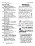
8 In addition, some low-endmanufacturers who do provide in-line ac protectors use ferritecore inductors to maintain a small sleek physical this approach works well when the Protection is merelyhandling power line noise, the inductor saturates under the mas-sive current of a real strike and the benefit of the inductancedisappears. Plastic housings and printed circuit boards shouldbe avoided where possible since they will most likely not holdup under real strike conditions when you need you are establishing a local zone of Protection for theradio room you need to choose an in-line ac power protector, asshown in Figure 8, that matches your voltage and current re-quirements. For most small to medium size stations, a single120 V ac protector with a capability of 15 or 20 A will satisfyall of our ac power needs.
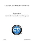
9 Each of the electronic items with anac power line extending beyond the circle should be aggregatedinto a single line as long as it is comfortably within the maxi-mum amperage of the selected protector (usually 15 or 20 A).Larger stations with high-power amplifiers or transmitter willmost likely have a separate 120 V ac or 240 V ac power circuitthat will require a separate ac power protector. Some high-endstations may require 100 A or 200 A in-line station ac is sent outside for convenience, for safety light-ing, or to run motors (not the common antenna rotator), thenthat ac circuit must be separately protected as it leaves theradio lines come in many types, but by far the mostcommon is the plain old telephone service (POTS).
10 This is abalanced line with a 48 V dc battery talk circuit and up to140 V ac ringing voltage. An in-line protector is the most ef-fective type for POTS with different types of protectors avail-able for different telephone line characteristics. One devicefor this purpose is shown in Figure word of caution many of the protectors on the marketuse modular connectors (RJ-11, -12, -45). While this is a greatconvenience for the installer, electrically this is a very fragileconnector and common amounts of surge energy are very likelyto destroy the connector by welding it or fusing it open. Inaddition, there are also issues of flammable plastic housings,ground wire characteristics, and printed circuit boards thatallow arcs to the equipment CircuitsControl circuits for all external devices must be protected,especially those that are tower-mounted.