Transcription of Sine Wave Generator Using Numerically Controlled ...
1 AN1523. Sine Wave Generator Using Numerically Controlled Oscillator Module Author: Vinaya Skanda . DIRECT DIGITAL SYNTHESIS (DDS). Microchip Technology Inc. AND NCO. Direct Digital Synthesis is a technique of generating an analog waveform, generally of sinusoidal wave shape INTRODUCTION from a time varying signal in its digital form and a DAC. A key requirement in most applications is the ability to The NCO module operates on the principle of DDS by generate and control waveforms at various repeatedly adding a fixed value to an accumulator.
2 The frequencies. Most common demands for such sources accumulator is 20 bits in length and additions occur at are industrial test setups for providing frequency the input clock rate, which can be a maximum of about stimulus, communication equipment with low-noise 16 MHz. The accumulator will overflow with a carry bit requirements, or medical testing devices. set periodically, and this will produce a transition in the The Direct Digital Synthesis (DDS) technique is gaining output of the NCO module. wide popularity and acceptance from the industrial The NCO module can operate in two modes: fixed duty community to achieve programmable analog outputs cycle PWM and frequency Controlled Pulse mode.
3 With with accuracy and high resolution. The traditional such an arrangement, the response will be very linear Pulse-Width Modulation (PWM), which is commonly across a wide range of frequencies, ranging from 0 kHz referred to as the poor man's Digital-to-Analog up to 500 kHz Using a clock of 16 MHz. The frequency Converter (DAC) was previously being used for this resolution that can be obtained is precise and is in purpose. The PWM method has the limitation of steps of 15 Hz across this entire frequency range. The generating arbitrary waveforms in low-frequency linear frequency control and the increased frequency ranges, which is overcome Using the DDS technique.
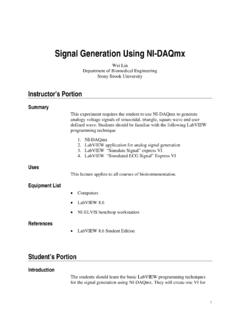
4 Resolution are the key distinguishing factors when This application note focuses on the use of the compared to the traditional PWM-based frequency Numerically Controlled Oscillator (NCO) module for control. Figure 1 illustrates the internal block diagram designing a Sine Wave Generator . The NCO module of the NCO module. uses the DDS technique for generating waveforms, and is available on various PIC16F family and PIC10F320/322 family of MCUs. For more information on other Core Independent Peripherals refer to 2013 Microchip Technology Inc.
5 DS00001523A-page 1. AN1523. FIGURE 1: INTERNAL BLOCK DIAGRAM OF NCO MODULE. Increment 16. 20. Clock Sources: Fosc 20 Single Pulse or Duty Cycle Controlled CLC Overflow Accumulator HF INTOSC. Ext. Pin Output S Q. To Pins, Interrupt, R Q Configurable Logic Cell (CLC), Complimentary Waveform Generator (CWG). Counter R. The NCO module generates precisely controllable output frequencies Using the DDS technique. The DDS. technique essentially provides a clock with carefully Controlled jitter on it. Therefore, it is necessary that the signal be aggregated on the frequency domain.
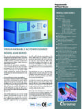
6 Figure 2 illustrates the typical output spectra when generating 50% duty cycle square wave Using the NCO. module. The sideband noise generated by the jitter is insignificant in comparison to the fundamental frequency. When plotted on a logarithmic scale, the NCO output compares to that of a perfect square wave. DS00001523A-page 2 2013 Microchip Technology Inc. AN1523. FIGURE 2: PERFECT SQUARE WAVE SPECTRUM COMPARED TO NCO OUTPUT SPECTRUM. Perfect Square Wave Spectrum NCO Output Spectrum 2013 Microchip Technology Inc. DS00001523A-page 3.
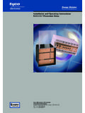
7 AN1523. NCO Output and PWM Output For an 8-bit PR2 register, the value can vary from 0. Comparison to 255. With the oscillator clock frequency being fixed, the value in the PR2 register determines the frequency This section provides the comparison between the of the PWM output. Since the PR2 register value forms NCO module and the traditional PWM module. When the denominator in Equation 1, any change in the value Using a PWM module to generate a pulse train with of PR2 will not yield a linear variation of FPWM, although variable frequency, use Equation 1 to calculate the the incremental change in the denominator or PR2 is PWM frequency.
8 Linear. Figure 3 illustrates the variation of PWM frequency with EQUATION 1: PWM FREQUENCY respect to a corresponding change in the PR2 value. CALCULATION. FOSC. F PWM = ---------------------------- 4 PR2 + 1 . Where, FPWM = Desired frequency of PWM. FOSC = Oscillator clock frequency PR2 = Period register to be loaded FIGURE 3: FREQUENCY vs PR VALUE IN PWM MODULE. The relation between the frequency of the NCO output EQUATION 2: PWM FREQUENCY. and the incremental register is provided in Equation 2. CALCULATION Using NCO. From Equation 2, note that FNCO is directly proportional MODULE.
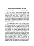
9 To the increment value, and the accumulator overflow FOSC. value is always fixed to 220 = 1048576. Therefore, any FNCO = ---------------------------------- IncrementValue . change in the increment value will yield a very linear Accumulator variation in the output frequency of the NCO ( , FNCO). Where, FNCO = Frequency of the output of NCO module FOSC = Oscillator clock frequency (about 16 MHz). Accumulator = 20 bit summing register that overflows to create an output transition Increment Value = Value loaded to change FNCO. DS00001523A-page 4 2013 Microchip Technology Inc.
10 AN1523. This concept illustrates the variation of FNCO with a corresponding change in the increment value, see Figure 4. FIGURE 4: FREQUENCY VERSUS INCREMENT VALUE IN NCO MODULE. Therefore, a better frequency resolution over a wide frequency range can be obtained Using the NCO for waveform generation, when compared to the conventional PWM-based approach. 2013 Microchip Technology Inc. DS00001523A-page 5. AN1523. PRINCIPLE OF SINE WAVE Fourier theorem assumes that the user add sine waves of infinite duration. Therefore, a square wave is GENERATION Using NCO MODULE.