Transcription of ULTRAFLOW type 65-S/65-R flow sensor - …
1 Installation Kamstrup A/S Industrivej 28, StillingDK-8660 Skanderborg TEL.: +45 89 93 10 00 FAX: +45 89 93 10 01 type 65-S/65-R1. InstallationPrior to installation of the flow sensor , the system should be flushed, and protection plugs/plastic diaphragms on the flow sensor should be removed. Correct placing of the flow sensor (flow and return) willappear from the front label of MULTICAL .The flow direction is indicated by an arrow on the side of the flow and gaskets are mounted as shown in the drawings overleaf. Pressure stage ofULTRAFLOW type 65-S/R: PN16/PN25/PN40, see sensor marking does not cover included of medium, ULTRAFLOW type 65-S/R: CMechanical environment: M1 (fixed installation with minimum vibration).Electromagnetic environment: E1 (housing/light industry). The meter s control cables must be drawn at min. 25 cm distance from other environment: Installation must take place in environments with non-condensing humidity as well as in a closed locations (indoors).
2 The ambient temperature must be within and repair: The flow sensor is verified separately and can, therefore, be separated from the calculator. Battery for replacement: Kamstrup type 66-00-200-100. Other repairs require subsequent reverification in an accredited can only be connected direct to Kamstrup s calculators on terminals 11-9-10, as shown in section Connection to other types of calculators require the use of a pulse : Please make sure that pulse/litres is identical on flow meter and the temperature of the medium exceeds 90 C, we recommendthe use of flange meters as well as wall mounting of MULTICAL .In order to prevent cavitation the working pressure at ULTRAFLOW must be min. bar at qp and min. bar at qs ( bar for DN80).This applies to temperatures up to approx. 80 C. ULTRAFLOW must not be exposed to lower pressure than the ambient pressure (vacuum).When the installation is complete, the water flow can be turned on. The valve on the inlet side must be opened Installation angle for ULTRAFLOW ULTRAFLOW DN100 ULTRAFLOW can be mounted horizontally, vertically or at an angle.
3 Important! In connection with ULTRAFLOW DN100, the plastic box containing the electronics must be placed on the side (when installed horizontally). Block diagramThe PULSE TRANSMITTER outlet11A GND 9A Supply ( VDC) 10A Signal Imax Connection exampleExample of connection between ULTRAFLOW and MULTICAL (battery supply).A functional control must be made, when installation of the entire energy meter is completed. Open thermostats and drain cocks to make the water flow in the heating system. Check that display values for temperature and water flow are Functional Electric connectionConnection to the PULSE TRANSMITTER5511-704 D1 ULTRAFLOW can be turned up to 45 (in relation to the pipe axis).Installation Kamstrup A/S Industrivej 28, StillingDK-8660 Skanderborg TEL.: +45 89 93 10 00 FAX: +45 89 93 10 01 type 65-S/65-R1. InstallationPrior to installation of the flow sensor , the system should be flushed, and protection plugs/plastic diaphragms on the flow sensor should be removed.
4 Correct placing of the flow sensor (flow and return) willappear from the front label of MULTICAL .The flow direction is indicated by an arrow on the side of the flow and gaskets are mounted as shown in the drawings overleaf. Pressure stage ofULTRAFLOW type 65-S/R: PN16/PN25/PN40, see sensor marking does not cover included of medium, ULTRAFLOW type 65-S/R: CMechanical environment: M1 (fixed installation with minimum vibration).Electromagnetic environment: E1 (housing/light industry). The meter s control cables must be drawn at min. 25 cm distance from other environment: Installation must take place in environments with non-condensing humidity as well as in a closed locations (indoors). The ambient temperature must be within and repair: The flow sensor is verified separately and can, therefore, be separated from the calculator. Battery for replacement: Kamstrup type 66-00-200-100. Other repairs require subsequent reverification in an accredited can only be connected direct to Kamstrup s calculators on terminals 11-9-10, as shown in section Connection to other types of calculators require the use of a pulse : Please make sure that pulse/litres is identical on flow meter and the temperature of the medium exceeds 90 C, we recommendthe use of flange meters as well as wall mounting of MULTICAL.
5 In order to prevent cavitation the working pressure at ULTRAFLOW must be min. bar at qp and min. bar at qs ( bar for DN80).This applies to temperatures up to approx. 80 C. ULTRAFLOW must not be exposed to lower pressure than the ambient pressure (vacuum).When the installation is complete, the water flow can be turned on. The valve on the inlet side must be opened Installation angle for ULTRAFLOW ULTRAFLOW DN100 ULTRAFLOW can be mounted horizontally, vertically or at an angle. Important! In connection with ULTRAFLOW DN100, the plastic box containing the electronics must be placed on the side (when installed horizontally). Block diagramThe PULSE TRANSMITTER outlet11A GND 9A Supply ( VDC) 10A Signal Imax Connection exampleExample of connection between ULTRAFLOW and MULTICAL (battery supply).A functional control must be made, when installation of the entire energy meter is completed. Open thermostats and drain cocks to make the water flow in the heating system.
6 Check that display values for temperature and water flow are Functional Electric connectionConnection to the PULSE TRANSMITTER5511-704 D1 ULTRAFLOW can be turned up to 45 (in relation to the pipe axis).Installation Kamstrup A/S Industrivej 28, StillingDK-8660 Skanderborg TEL.: +45 89 93 10 00 FAX: +45 89 93 10 01 type 65-S/65-R1. InstallationPrior to installation of the flow sensor , the system should be flushed, and protection plugs/plastic diaphragms on the flow sensor should be removed. Correct placing of the flow sensor (flow and return) willappear from the front label of MULTICAL .The flow direction is indicated by an arrow on the side of the flow and gaskets are mounted as shown in the drawings overleaf. Pressure stage ofULTRAFLOW type 65-S/R: PN16/PN25/PN40, see sensor marking does not cover included of medium, ULTRAFLOW type 65-S/R: CMechanical environment: M1 (fixed installation with minimum vibration).Electromagnetic environment: E1 (housing/light industry).
7 The meter s control cables must be drawn at min. 25 cm distance from other environment: Installation must take place in environments with non-condensing humidity as well as in a closed locations (indoors). The ambient temperature must be within and repair: The flow sensor is verified separately and can, therefore, be separated from the calculator. Battery for replacement: Kamstrup type 66-00-200-100. Other repairs require subsequent reverification in an accredited can only be connected direct to Kamstrup s calculators on terminals 11-9-10, as shown in section Connection to other types of calculators require the use of a pulse : Please make sure that pulse/litres is identical on flow meter and the temperature of the medium exceeds 90 C, we recommendthe use of flange meters as well as wall mounting of MULTICAL .In order to prevent cavitation the working pressure at ULTRAFLOW must be min. bar at qp and min. bar at qs ( bar for DN80).This applies to temperatures up to approx.
8 80 C. ULTRAFLOW must not be exposed to lower pressure than the ambient pressure (vacuum).When the installation is complete, the water flow can be turned on. The valve on the inlet side must be opened Installation angle for ULTRAFLOW ULTRAFLOW DN100 ULTRAFLOW can be mounted horizontally, vertically or at an angle. Important! In connection with ULTRAFLOW DN100, the plastic box containing the electronics must be placed on the side (when installed horizontally). Block diagramThe PULSE TRANSMITTER outlet11A GND 9A Supply ( VDC) 10A Signal Imax Connection exampleExample of connection between ULTRAFLOW and MULTICAL (battery supply).A functional control must be made, when installation of the entire energy meter is completed. Open thermostats and drain cocks to make the water flow in the heating system. Check that display values for temperature and water flow are Functional Electric connectionConnection to the PULSE TRANSMITTER5511-704 D1 ULTRAFLOW can be turned up to 45 (in relation to the pipe axis).
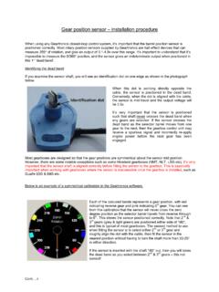
9 Straight inletStraight inlet: ULTRAFLOW requires neither straight inlet nor outlet to meet the Measuring Instruments Directive (MID) 2004/22/EC, OIML R75:2002 and EN 1434:2007. Only in case of heavy flow distur-bances before the meter will a straight inlet section be necessary. We recommend to follow the guidelines in CEN CR 13582. 2. Examples of installationThreaded meter with MULTICAL /PULSE TRANSMITTER mounted on ULTRAFLOW .Short direct sensor mounted in ULTRAFLOW (only G (R ) and G1 (R )) and glands fitted on the from rightFlow from leftGasketGasketTightening approx. 4 NmFlange meter with MULTICAL /PULSE TRANSMITTER mounted on ULTRAFLOW Please note: For meters DN100, MULTICAL or PULSE TRANSMITTER cannot be mounted on the flow Electric connectionULTRAFLOW MULTICAL Blue (GND)/11A 11 Red (supply) 9A 9 Yellow (signal)/10A 10 Flow from leftFlow from rightConnection:MULTICAL and ULTRAFLOW ( ULTRAFLOW is supplied from MULTICAL )4. Voltage supply of PULSE TRANSMITTERThe PULSE TRANSMITTER can be supplied through a built-in lithium battery, a 24 VAC internal mains module or an internal 230 VAC mains two wires on the battery or the mains module are mounted in terminal strips nos.
10 60 and 61. The polarity must be correct; red wire to terminal no. 60 (+) and black wire to terminal no. 61 (-). Battery supplyThe PULSE TRANSMITTER is connected to a lithium battery, D-cell. The battery is marked with installation year, 2007, and manu-facturing battery lifetime is obtained by keeping the battery temperature below 30 C, in connection with voltage of a lithium battery is almost constant throughout the entire battery lifetime (approx. V). Thus, it is not possible to measure the remaining capacity of the battery must neither be charged nor short-circuited. Used batteries must be disposed of with consideration to the Mains modulesThe modules are under protection class II and are connected through a two-wire cable (without ground) through the cable nipple of the calcu-lator, which is placed at the bottom on the right-hand side of the base unit. Use a feeder cable with an outer diameter of 5 10 mm and ensure cor-rect dismantling and mounting of cable relief. Max.