Transcription of RadioRA 2 Main Repeater INSTALLATION (044316)
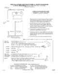
1 English Dimensions (front view) Wired and RF Configuration Troubleshooting Guide*. Measurements are shown as: in (mm). main or Auxiliary Repeater Symptom Probable Cause and Action INSTALLATION Instructions Please Read Before Installing See table below Dimmers, Power Not Present main Repeater DC Adapter keypads, Ensure that the power supply cord is plugged into a (16) and shades / wall outlet and the power jack on the main Repeater . RR- main -REP-WH Included (T120-9DC-3-BL) 30 ft (9 m) 30 ft (9 m) 30 ft (9 m). RRK- main -REP-WH Not included (TE240-9DC-3-XX, TU240-9DC-3-XX) maximum maximum maximum draperies do Circuit Breaker is OFF or tripped.
2 Reset or turn on RR- main -REP-WHBA, RRM- main -REP-WH, not respond circuit breaker. Not included (see LutronR P/N 369561). RRN- main -REP-WH, RRQ- main -REP-WH main Repeater to the main Devices not programmed as part of a system. Repeater . main Repeater : 9 V- 300 mA Program the main Repeater and all other devices DC Adapter: Power Jack (to DC adapter) (IEC PELV / NECR Class 2) according to the system Setup Guide. RF Link T120-9DC-3-BL: Input: 120 V~ 60 Hz W Output: 9 V- 300 mA Mounting Wired Link 1000 ft 60 ft (18 m). TE240-9DC-3-XX: Input: 100 240 V~ 50/60 Hz A Output: 9 V- 300 mA.
3 Repeater Status (305 m) maximum maximum System devices are not within specified RF range. hole M 1 2 3 4. TU240-9DC-3-XX: Input: 100 240 V~ 50/60 Hz A Output: 9 V- 300 mA detail Ensure that dimmers, keypads and shades / draperies Typical power consumption: W. Communication Typical Power Consumption test conditions: one LED on, Ethernet cable plugged in, ( ) RF Wired ( ) Connection RF range: are within 30 ft (9 m) of a Repeater . Setup Verify that all Repeaters are within 60 ft (18 m) of Repeater powered by the 9 V - adapter (T120-9DC-3-BL). Test Add To Repeater 60 ft (18 m).
4 Another Repeater . To other devices 30 ft (9 m). Use these instructions to install the model numbers listed above. For system Setup Guide and tools visit: (70). Power Repeater Link Integrate Program / Integrate Operation* Repeater Status LEDs Features Antena N/C. MUX. MUX. COM. 9V. Displays the status of 2 3 4 RS232 Ethernet 1. main Repeater Supports system setup and ensures error-free communication between system components. Mounting holes the Repeaters in the ( ) system. Add up to (4) Auxiliary Repeaters to extend range for larger system applications. ( ) dia. Test button: enters the system diagnostic mode.
5 ( ). dia. Repeater Status RF and wired LEDs V erify that the Repeaters in a system are communicating effectively. M 1 2 3 4. Displays the Tx / Rx Add button: enters the system address mode. Communication (108) RF Wired activity on the RF and Allows new devices to be easily added into a system. Front Buttons Setup wired links. RS485 port to connect to other Repeaters through a wired link (daisy-chain). Test Add Repeater Status Model Dimension Wired Link (Daisy-chain) (Green=Tx; Orange=Rx). RS232 port for integration. M 1 2 3 4. Maximum 1000 ft (305 m) IEC PELV/NECR Class 2.
6 Ethernet port for integration and PC connectivity. RR- main -REP-WH, Two pair one pair 18 AWG ( mm2), one pair 18 to 22 AWG Power Repeater Link Integrate Program / Integrate Test and Add Buttons Communication N/C. MUX. MUX. COM. 9V. RR- main -REP-WHBA, ( ) ( to mm2) twisted shielded. 1 2 3 4 RS232 Ethernet Press and hold to enter Important Notes RRQ- main -REP-WH the system into Test RF Wired Environment MUX mode or Add mode. Ambient operating temperature: 32 F to 104 F (0 C to 40 C), 0% to 90% humidity, RRK- main -REP-WH, CAT5 Cable: MUX maximum Setup non-condensing. Indoor use only.
7 RRN- main -REP-WH, ( ) N/C Test Add Test and Add LEDs Codes RRM- main -REP-WH Front Buttons 328 ft (100 m) Test Add Flashes green to COM indicate that the Install in accordance with all local and national electrical codes. system is in Test mode Cleaning or Add mode. To clean, wipe with a clean damp cloth. DO NOT use any chemical cleaning solutions. DC Adapter Power Mounting Diagram (side view) 9V RS232 Ethernet NOTICE: Using a DC adapter not rated at the proper specifications could damage the Vertical Horizontal * Note: Refer to the system Setup Guide for additional troubleshooting suggestions and LED feedback.
8 Repeater and possibly overheat the DC adapter. Use only the DC adapter that meets the specification listed above. Ceiling RS485. For California residents only The batteries in these devices contain Perchlorate Material special handling may apply. Returning a main Repeater to Factory Settings For more information visit Power Jack (to DC adapter) RS232 Cable: Note: Returning a main Repeater to factory settings will erase all RF Device Placement (IEC PELV/NECR Class 2) maximum 50 ft programming from it and all devices and will require the main Repeater to #6 (M3) screw All dimmers, switches, keypads and shades / draperies must be located within 30 ft (15 m) be reprogrammed into the system.
9 Recommended (9 m) of a Repeater . All Repeaters must be within 60 ft (18 m) of another Repeater . 1. Triple tap and hold the Test button on a main Repeater . DO NOT release Wall (2 included). Programming the button after the third tap. For programming instructions, see the system Setup Guide included with the main 87654321 2. K. eep the Test button pressed on the third tap until all the LEDs start to Repeater or visit the website listed above. flash red slowly (approximately 3 seconds). RS232 and Ethernet Pin Numbering 3. R. elease the Test button and immediately triple tap it again.
10 All the LEDs INSTALLATION will flash red quickly. When the LEDs stop flashing, the main Repeater 1. Find a suitable location for the main Repeater . For more information regarding the proper has been returned to factory settings placement of a main Repeater in a system see the system Setup Guide. 6 7 8 9. ount vertically or horizontally, as shown in the Mounting Diagram, using two #6 (M3). 2. M Level Surface 1 2 3 4 5. 87654321. screws (included). When mounting, allow 7 in ( mm) clearance for the antenna and ensure convenient access to the power plug. In order to achieve proper RF performance, ( ) Warranty: For warranty information, please see the Warranty enclosed do not mount unit in a metal enclosure.