Transcription of Technical Instructions - Watts Water
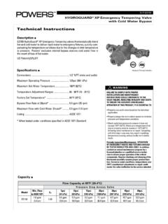
1 The e423 HydroGuard T/P automatically mixes hot and cold Water to deliver blended Water within a specified range. Using an advanced ther-mal actuator, the e423 quickly compensates for temperature fluctuations induced by Water temperature and pressure changes. In the event of cold Water failure, the thermostatic motor virtually shuts of the flow of hot e423 features heavy cast-brass construction and all parts are acces-sible from the front of the valve and are corrosion resistant. The unit also features a metal-to-metal temperature limit stop, and all e423 valves open in the cold Water position to ensure maximum bather safety and accuracy, reliability and Water economy of the e423 HydroGuard make it preferable for applications that require precise, consistent Water control: showers, baths, hospital hydrotherapy and residential HydroGuard e423 valves and shower systems can be selected to meet the Americans with Disabilities Act (ADA).Description nHydroGuard T/PSeries e423 Combination Tempering Valve Model 1 Technical InstructionsIS-P-e423 Advanced Thermal ActivationSpecifications n* At 45 psi differential [310 kPa], with hot Water supply between 140 180 F [60 82 C].
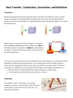
2 50/50 Series e423 thermostatic mixing valves meet above perfor-mance specifications based on typical operating conditions as stated in ASSE 1016 [45 psi pressure differential, hot Water supply between 140 -180 F (60 -82 C), cold Water supply less than 70 F (21 C)].If your operating conditions vary from those stated in the standard, per-formance may vary as well. Consult your local sales representative or the Powers Technical support department @ , Press "2" to discuss your specific application. All Powers thermostatic mixing valves perform to the requirements of standards ASSE 1016 Type T/P and CSA e423320100908070605040302010123456789101 112 Pressure Drop in Rate in gpm Qualifier is 10%(without checkstops or showerhead)Flow Rate in L/min Qualifier is 10%(without checkstops or showerhead)Pressure Drop in kPaStandardCapacity1/2 NPT Tempered Water Outlet1/2 NPT Hot Water Inlet3-3/4 in. [94mm] 1/2 NPT cold Water Inlet 4-1/8 in. [104mm] 1-1/4 in. [32mm] 2 in. [51mm] 2-1/8 in.
3 [53mm] e423 Type BType FConnections: Type e423 .. 1/2" NPT Inlets and 1/2" NPT Top OutletCapacity (without checkstops) .. gpm [ L/min]* ( gpm [ L/min])Maximum Hot Water Supply Temperature .. 190 F [88 C]Minimum Hot Water Supply Temperature (not applicable to low temperature hot Water valves) .. 5 F [14 C] above set pointMaximum Operating Pressure .. 125 psig [862 kPa]Temperature Ranges: ASSE 1016 Type T .. 65-115 F [18-46 C] ASSE 1016 Type T/P .. 90-110 F [32-43 C]Temperature Limit Stop .. Adjustable* (factory set at 110 F [43 C])Maximum Static Pressure .. 125 psig [862 kPa]Minimum Flow and Pressure Differential: .. 1 gpm [ L/min]Certification .. CSA B125 Compliance .. ASSE 1016 T/PShipping Weight .. 5 lbs. [ kg]Operation nModel Identification nPreventative Maintenance n2 NOTE: Before servicing checkstops or piping, always turn off the upstream Water 12 MONTHS:Open up the checkstops and check for free movement of the poppet. To access the checkstops, remove the valve handle assembly and dial servicing, turn off the Water supply upstream.
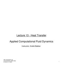
4 To close the checkstops, turn the adjustment screw fully clock-wise on each the valve bonnet and rinse all grit and impurities from the internal valves that are used outdoors. Remove and store the internal components and drain all Water from the 3 MONTHS:Every three months, check the maximum temperature setting (handle rotation setting).Nameplate StampABTo be sure you order and install the appropriate parts into your valve, first determine the correct model number and temperature range of your valve. The temperature range of the valve is stamped on a nameplate (A). In the example, "115F" is model number is the first digit of the four-digit date code stamped on the nameplate (B).In the example, the date code starts with an 9, so the model number is and cold Water enter respective ports in the valve and mix in a chamber containing an advanced thermal actuator (refer to cutaway view). This actuator senses and maintains the set point of the the adjustment handle repositions the shuttle in the car-tridge assembly to produce the desired temperature.
5 The mixed Water passes over the shutoff disc to the outlet. If the hot or cold supply Water temperature or pressure changes, the thermal actuator will contract or expand. This movement repositions the shuttle to maintain the desired temperature. With the adjustment handle in full clockwise (OFF) position, the shutoff disc closes the mixing chamber from the Temperature limit stop limits the movement of the control handle. The standard HydroGuard e423 valve is factory set to deliver tempered Water up to 110 F [43 C] with equal supply pressures, with hot Water temperature 140 F [60 C], cold Water temperature 60 F [ C]. cold Water SupplyHot Water SupplyShuttleAdvance Thermal ActuatorTemperature Limiting StopCartridge Assembly3 Servicing nTo Disassemble:1. Turn off hot & cold Water supply-stops2. Remove the handle and trim plate3. Remove 4 bonnet screws and bonnet assembly4. Remove all internal components from valve body5. At this point you should have an empty valve : After completing any maintenance/repairs, reset the high temperature limit Reassemble:1.
6 Ensure the inside of the valve body is free of deposits and debris. Clean as Push the cartridge into the body without the O-rings installed. The cartridge should slide in easily, and bottom out with its large fins just inside the front surface of the casting. If the cartridge is difficult to install, or does not go in all the way, remove the cartridge and clean the body or remove any obstructions. Repeat this step until the cartridge installs Remove the cartridge and install the 2 O-rings. Lubricate the O-rings with silicon Install the cartridge back into the body. The cartridge should go in until the large fins are just inside the front surface of the casting (same position as in step 2). If you cannot push it in all the way due to O-rings, use bonnet and two (2) screws to force Place the wax element into the stem assembly, stem side first, and place this bonnet-stem-motor assembly into/onto the valve body. Rotate the bonnet assembly to line up the bonnet screw holes and reinstall and tighten the four bonnet With handle, rotate the stem assembly clockwise, until it bottoms out on the cartridge.
7 At this point your valve is in the off Turn the hot and cold Water supplies back on and verify there is no leakage. 8. Verify proper operation by rotating the stem from the off position, counterclockwise, to the high temperature posi-tion. Verify the temperature does not exceed your desired maximum temperature. Rotate stem back to the off Leave the adjusting stem in the full hot position to determine the high temperature limit stop is set properly. If not, set the maximum Temperature SettingThe high temperature limit stop is threaded onto the bonnet. Turn counterclockwise to increase setting and clockwise to decrease setting. Powers recommends a maximum setting of 110 F (43 C). To adjust temperature, rotate handle to the maxi-mum desired outlet temperature, screw temperature limit stop until it touches stem's shoulder. Close valve and open it to verify Install cover plate and handle with the screw that the handle set screw lines up with the groove on the adjustment Guidelines nAdherence to these guidelines and recommendations promotes safe product use and ensures proper valve Thermostatic Water mixing valves are control devices which must be cleaned and maintained on a regular basis.
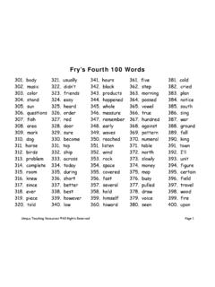
8 Powers specifies periodic maintenance at least once a year or imme-diately after any changes are made to the plumbing system. Annual cleaning and inspection is recommended, however, frequency of cleaning depends on quality of local Water conditions. Refer to the Preventive Maintenance section for recommended cleaning WARNING: To prevent injury to the user, it is important to periodically check the maximum temperature adjustment on the Quick closing valves may cause damage to the mixing valve by creating shock waves. When the HydroGuard sup-plies tempered Water to self-closing and/or solenoid valves, Powers recommends installing a shock absorber (Powers Part #460-353) on the discharge line, which will protect the HydroGuard from Position the e423 valve as close as possible to outlet fixture to avoid waste of energy and Water (except in applications where the valve is used as a primary mixing valve).USA: Phone: Fax : Phone: Fax 1039 EDP# 6512294 2010 PowersA Watts Water Technologies CompanyTroubleshooting n123456 Item Part# Description1 420049 Handle Kit2 420103 Trim Kit3 420108 Bonnet Kit4 420024 Wax Element5 420452 Cartridge Kit6 N/A BodyIndexPart #Description1420 049 Handle Kit2420 103 Trim Kit3420 108 Bonnet Kit4420 024 Wax Element5420 452 Cartridge Kit6N/ABodyParts List - e423 Model 1 nWhat to look for if:The maximum temperature cannot be Lime deposits may have accumulated in the hot Water pipes, restricting the hot Water The hot Water supply temperature may be too The temperature limit stop setting may be too low.
9 Remove valve handle, and readjust the temperature limit stop. Flow of Water is less than The upstream supply valves may not be fully The inlet supply pressure(s) may be Lime deposits may have accumulated in cartridge, restricting Water The showerhead may be clogged. Remove and The checkstops may be clogged. Clean check valve opens with hot Water flow rather than cold Water The inlet Water supplies are connected to the wrong ports. Remove the valve and reinstall. Flow of Water is completely shut The upstream supply valves may be completely The hot or cold Water supply pressure may have failed. The HydroGuard e423 valve is designed to reduce the flow of Water upon either supply The checkstops may be closed. Access the checkstops and open by turning the adjustment screw fully nThe Seller warrants that the equipment manufactured by it and covered by this order or contract is free from defects in material and workmanship and, without charge, equipment found to be defective in material or workmanship will be repaired, or at Seller s option replaced original point of shipment, if written notice of failure is received by Seller within one (1) year after date of shipment (unless specifically noted elsewhere), provided said equipment has been properly installed, operated in accordance with the Seller s Instructions , and provided such defects are not due to abuse or decomposition by chemical or galvanic action.
10 ThiS expreSS warranTy iS in lieu OF and excludeS all OTher warranTieS, guaranTeeS, Or repreSenTaTiOnS, expreSS OF implied. There are nO implied warranTieS OF merchanTaBiliTy Or OF FiTneSS FOr a parTicular purpOSe. The Seller assumes no responsibility for repairs made on the Seller s equipment unless done by the Seller s authorized personnel, or by written authority from the Seller. The Seller makes no guarantee with respect to material not manufactured by it.