Transcription of installation and getting started guide - ftp.hp.com
1 Hpprocurveseries 2300 and 2500 switchesinstallation andgetting started ProCurveSeries 2300 and 2500 SwitchesInstallation and getting started Page i Friday, February 9, 2001 6:00 PMHewlett-Packard Company8000 Foothills Boulevard, m/s 5552 Roseville, California 95747-5552 Copyright 2000, 2001 Hewlett-Packard CompanyAll Rights document contains information which is protected by copyright. Reproduction, adaptation, or translation without prior permission is prohibited, except as allowed under the copyright Number5969-2353 Edition 2 March 2001 Applicable ProductsSeries 2300: HP procurve Switch 2312 (J4817A) HP procurve Switch 2324 (J4818A)Series 2500: HP procurve Switch 2512 (J4812A) HP procurve Switch 2524 (J4813A)DisclaimerThe information contained in this document is subject to change without COMPANY MAKES NO WARRANTY OF ANY KIND WITH REGARD TO THIS MATERIAL, INCLUDING, BUT NOT LIMITED TO, THE IMPLIED WARRANTIES OF MERCHANTABILITY AND FITNESS FOR A PARTICULAR PURPOSE.
2 Hewlett-Packard shall not be liable for errors contained herein or for incidental or consequential damages in connection with the furnishing, performance, or use of this assumes no responsibility for the use or reliability of its software on equipment that is not furnished by the Customer Support/Warranty booklet included with the copy of the specific warranty terms applicable to your Hewlett-Packard products and replacement parts can be obtained from your HP Sales and Service Office or authorized dealer. SafetyBefore installing and operating these products, please read the installation Precautions in chapter 2, Installing the Switch 2300 and 2500 , and the safety statements in appendix C, Safety and Regulatory Statements . Page ii Friday, February 9, 2001 6:00 PMiiiContents1 Introducing the HP procurve Series2300 and 2500 SwitchesFront of the Switches .. 1-2 Network Ports .. 1-2 LEDs.
3 1-3 Mode LED Select Button and Indicator LEDs .. 1-5 Console Port (Series 2500 Switches only) .. 1-6 Download Port (Series 2300 Switches only) .. 1-6 Reset Button .. 1-6 Clear Button (Series 2500 only) .. 1-7 Back of the Switches .. 1-7 Power Connector .. 1-7 Switch Features .. 1-8 Switch Operation Overview .. 1-9 Address Table Operation .. 1-9 Effect of VLANs (Series 2500 only) .. 1-102 Installing the Series 2300 and 2500 SwitchesIncluded Parts .. 2-1 installation Procedures .. 2-2 Summary .. 2-2 installation Precautions: .. 2-31. Prepare the installation Site .. 2-42. Install Transceivers (optional) .. 2-63. Verify the Switch Passes Self Test .. 2-7 LED Behavior: .. 2-84. Mount the Switch .. 2-9 Rack or Cabinet Mounting .. 2-9 Horizontal Surface Mounting .. 2-12 Wall Mounting .. Page iii Friday, February 9, 2001 6:00 PMiv5. Connect the Switch to a Power Source.
4 2-136. Connect the Network Cables .. 2-14 Using the RJ-45 Connectors (10/100 Base-TX ports) .. 2-14 Connecting Cables to the Transceivers .. 2-147. (Optional) Connect a Console to the Switch 2500 .. 2-15 Terminal Configuration .. 2-15 Connecting a Console .. 2-16 getting started With Switch Configuration (Series 2500 Switches Only) .. 2-17 Recommended Minimal Configuration .. 2-17 Using the Console Setup Screen .. 2-18 Where to Go From Here .. 2-20 Using the IP Address for Remote Switch Management (Series 2500 Switches Only) .. 2-20 Starting a Telnet Session .. 2-20 Starting a Web Browser Session .. 2-21 Sample Network Topologies .. 2-22As a Desktop Switch .. 2-22As a Segment Switch .. 2-23 Connecting to a Backbone Switch .. 2-24 Stacking the Switches (Series 2500 only) .. 2-253 TroubleshootingBasic Troubleshooting Tips .. 3-1 Diagnosing with the LEDs .. 3-4 Proactive Networking.
5 3-8 Hardware Diagnostic Tests .. 3-9 Testing the Switch by Resetting It .. 3-9 Checking the Switch LEDs .. 3-9 Checking Console Messages (Series 2500 switches only) .. 3-9 Testing Twisted-Pair Cabling .. 3-10 Testing Switch-to-Device Network Communications .. 3-10 Testing End-to-End Network Communications .. 3-10 Restoring the Factory Default Configuration (Series 2500 switches only) .. Page iv Friday, February 9, 2001 6:00 PMvDownloading New Code (Series 2300 switches only) .. 3-12To Perform the Download: .. 3-12HP Customer Support Services .. 3-13 Before Calling Support .. 3-13A SpecificationsPhysical .. A-1 Electrical .. A-1 Environmental .. A-1 Acoustic .. A-2 Connectors .. A-2 Safety .. A-2B Switch Ports and Network CablesSwitch Ports .. B-1 Twisted Pair .. B-1 Fiber-Optic .. B-1 Cables .. B-2 Twisted-Pair Cable/Connector Pin-Outs.
6 B-3 Straight-Through Twisted-Pair Cable for10 Mbps or 100 Mbps Network Connections .. B-5 Cable Diagram .. B-5 Pin Assignments .. B-5 Crossover Twisted-Pair Cable for10 Mbps or 100 Mbps Network Connection .. B-6 Cable Diagram .. B-6 Pin Assignments .. B-6 Straight-Through Twisted-Pair Cable for1000 Mbps Network Connections .. B-7 Cable Diagram .. B-7 Pin Assignments .. B-7C Safety and EMC Regulatory StatementsSafety Information .. C-1 EMC Regulatory Statements .. Page v Friday, February 9, 2001 6:00 Page vi Friday, February 9, 2001 6:00 PM1-1 Introducing the HP procurve Series 2300 and 2500 1 Introducing the HP procurve Series2300 and 2500 SwitchesThe HP procurve Series 2300 and 2500 Switches are multiport high-speed switches that can be used to build high-performance switched workgroup networks. These switches are store-and-forward devices that offer low latency for high-speed networking.
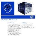
7 With these switches you can directly connect computers, printers, and servers to provide dedicated bandwidth to those devices, and you can build a switched network infrastructure by connecting these switches to hubs, other switches, or routers. In addition, the Series 2500 Switches offer full network management chapter describes your HP Series 2300 and 2500 Switches including: Front and back of the switches Features Switch operation overviewThroughout this manual, these switches will be abbreviated as the Series 2300 Switches and Series 2500 Switches , or when common features are being described, as the Series 2300 and 2500 Switches . ! "#$% &'# " ( ) " ( & *" ( & *+ ,#-" - , ) ! ) . # / ( 0 ! / , ! ) 1 ! . ! ( ! "#$% &'# " ( ) " ( & *" ( & *+ ,#-" - , ) ! ) . # / ( 0 ! / , ! ) 1 ! . ! ( HP procurve Switch 2312(J4817A)HP procurve Switch 2324(J4818A) !))
8 "#$% &'# " ( ) " ( & *" ( & *+ ,#-" - , ) ! ) . 2 0 ! 2 / , ! ) 1 ! . ! ( ! "#$% &'# " ( ) " ( & *" ( & *+ ,#-" - , ) ! ) . 2 0 ! 2 / , ! ) 1 ! . ! ( HP procurve Switch 2512(J4812A)HP procurve Switch 2524(J4813A)Series 2300 SwitchesSeries 2500 Page 1 Friday, February 9, 2001 6:00 PM1-2 Introducing the HP procurve Series 2300 and 2500 SwitchesFront of the SwitchesIntroducing the HP procurve Series 2300 and 2500 Front of the SwitchesNetwork Ports 12 or 24 autosensing 10/100 Base-TX these ports have the HP Auto MDIX feature, which means that you can use either straight-through or crossover twisted-pair cables to connect any network devices to the switch. Two transceiver slots for installing any of the supported gigabit and 100 Mbps transceivers. ! "#$% &'# " ( ) " ( & *" ( & *+ ,#-" - , ) ! ) . 2 0 ! 2 / , ! ) 1 ! . ! ( !
9 "#$% &'# " ( ) " ( & *" ( & *+ ,#-" - , ) ! ) . # / ( 0 ! / , ! ) 1 ! . ! ( Reset and Clear buttonsDownloadportMode Select buttonand indicator LEDsLink and Mode LEDs for switch ports10/100 Base-TX RJ-45 ports*Self Test and Fan Status LEDsPower and Fault LEDsHP procurve Switch 2524HP procurve Switch 2324 Slots forGigabit or 100 Mbps transceiversConsole Port10/100 Base-TX RJ-45 ports** All 10/100 Base-TX RJ-45 ports have the HP Auto MDIX Page 2 Friday, February 9, 2001 6:00 PM1-3 Introducing the HP procurve Series 2300 and 2500 SwitchesFront of the SwitchesIntroducing the HP procurve Series 2300 and 2500 LEDsTable LEDsSwitch LEDsStateMeaningPower(green)OnThe switch is receiving switch is NOT receiving (orange)OffThe normal state; indicates that there are no fault conditions on the A fault has occurred on the switch, one of the switch ports, or the fan. The Status LED for the component with the fault will blink briefly after the switch is powered on or reset, at the beginning of switch self test.)
10 If this LED is on for a prolonged time, the switch has encountered a fatal hardware failure, or has failed its self test. See chapter 3, Troubleshooting for more Test(green)OffThe normal operational state; the switch is not undergoing self switch self test and initialization are in progress after you have power cycled or reset the switch. The switch is not operational until this LED goes off. The Self Test LED also comes on briefly when you hot swap a transceiver into the switch; the transceiver is self tested when it is hot A component of the switch has failed its self test. The status LED for that component, for example an RJ-45 port, and the switch Fault LED will blink Select (3 green LEDs)ActIndicates that the port Mode LEDs are displaying network activity that the port Mode LEDs are lit for ports that are in Full Duplex that the port Mode LEDs are lit for ports that are operating at their maximum possible link speed.