Transcription of Temperature Measurement with a Thermistor and an …
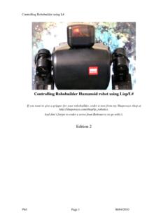
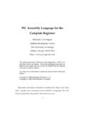
1 Temperature Measurement with aThermistor and an ArduinoClass Notes for EAS 199 BGerald Recktenwald May 25, 20131 Measuring the Thermistor SignalA Thermistor indicates Temperature by a change in electrical resistance. Theanalog input pins of the Arduino can only measure voltage, so the electricalresistance of a Thermistor cannot be measured directly1. A simple technique forconverting the (variable) resistance of the Thermistor to a voltage is to use thethermistor in a voltage divider, as shown in the left side of Figure 1. The rightside of Figure 1 is a representation of the voltage divider circuit connected toan voltage divider has two resistors in series. In the left side of Figure 1, theupper resistor is the Thermistor , with variable resistanceRt.
2 The lower resistorhas a fixed resistanceR. A voltageVsis applied to the top of the circuit2. Theoutput voltage of the voltage divider isVo, and it depends onVsandR, whichare known, andRt, which is variable and unknown. As suggested by the wiringdiagram in the right side of Figure 1,Vois measured by one of the analog inputpins on the The Voltage DividerA voltage divider is a standard configuration of resistors. In this section wederive the simple equation that relatesV0,Vs, two resistors in series share the same current,I. The voltage drop acrossthe two resistors isVs=I(R+Rt)(1) Mechanical and Materials Engineering Department,Portland State University,Portland,OR, resistance is always measured indirectly, usually by inferring the resistance froma measured voltage drop.
3 Precision resistance measurements involve techniques different fromthose described in these notes. Multimeters and other instruments that measure resistancehave built-in circuits for measuring the voltage drop across a resistor when a precisely con-trolled and measured current is applied to the the instructions for its data logging shield, adafruit recommends using the inputto power sensors because because the 5V line is noisey. To use the line, the signal istied to theArefpin. In myinformal experiments, there was no apparent difference between the and 5V 199B Thermistor Measurement2 VsVoRtRFigure 1: Voltage divider circuit (left) and sample breadboard wiring (right) formeasuring voltage to indicate Thermistor resistance. For the breadboard wiringon the right,Vois measured with analog input Pin the voltage drop across the fixed resistor isVo=IR(2)Solve Equation (1) and Equation (2) forIand set the resulting equations equalto each otherI=VsR+RtandI=VoR= VsR+Rt=VoRThe last equality can be rearranged to +Rt(3)Rearranging Equation (3) to solve forRtgivesRt=R(VsVo 1).
4 (4)Equation (4) is used to compute the Thermistor resistance from the MeasuringRtandTwith an ArduinoIn this section a series of Arduino sketches are developed for measuring thethermistor output. The reader is assumed to be familiar with writing and run-ning code on an Arduino. The sketches start with a simple printing of voltageand resistance, and progress to a reusable Thermistor object that can easily beincorporated into other sketches presented here can be adapted to work with any specific implementation here uses an Cantherm MF52A103J3470 NTC ther-mistor with a nominal resistance of 10 k at 21 C. The fixed resistor is a nom-inal 10 k resistor . For any specific Thermistor you will need a fixed resistorG. 25, 2013 EAS 199B Thermistor Measurement3of nominally equal resistance, and a calibration equation for resistance as afunction of code for these sketches was developed after reading the sample codeon the Arduino support site3.
5 The purpose of this document is to provide anintroduction to Arduino programming by using the Thermistor Measurement asa case study. The pace will probably be too slow for readers already famil-iar with Arduino programming. Readers looking for code to incorporate intotheir sketches should focus on Section ,A Reusable Thermistor FunctionandSection ,A Reusable Thermistor First Step: MeasuringVoand in Listing measures andprintsVo, the voltage across the fixed resistor . The Thermistor resistance com-puted from Equation (4) is also are two main sections : thesetupfunction and theloopfunction. These two functions are required in allArduino sketches. Thesetupfunction establishes communication parameterswith the host computer before running the main setup() { (9600); // open serial port and set data rate to 9600 (" Thermistor voltage and resistance Measurement :"); ("\n Vs Vo Rt");} (9600)statement sets the communication speed between theboard and the host computer to be 9600 bits per second.
6 The add labels to the serial monitor screen at the start of program is where the main work of the program occurs. Theloopfunction begins with variable declarations and the assignment of ThermistorPin = 1; // Analog input pin for Thermistor voltageint Vo; // Integer value of voltage readingfloat R = ; // Fixed resistance in the voltage dividerfloat Rt; // Computed resistance of the thermistorThe voltage reading is stored inVoas an integer because theanalogReadfunc-tion returns integers between 0 and 1023. TheRandRtvariables are floatingpoint type because we want store the result of computingRtwith Equation (4)using maximum middle of theloop()function consists of the call to theanalogReadfunction, and the direct evaluation of Equation (4).
7 Vo = analogRead(SensePin);Rt = R*( / float(Vo) - );The evaluation ofRtis a direct translation of Equation (4). On a 10 bit scale, is the value corresponding toVs, the maximum possible value of thevoltage, which is 5V. Thefloat(Vo)expression converts the integer value storedinVoto floating point numbers before the division is performed. Consider thedifference between integer and floating point math whenVo= In particular, the code here ismost similar to the second version of the Thermistor implementation, 25, 2013 EAS 199B Thermistor Measurement4// File: Use a voltage divider to indicate electrical resistance of a -- setup() is executed once when sketch is downloaded or Arduino is resetvoid setup() { (9600); // open serial port and set data rate to 9600 (" Thermistor voltage and resistance Measurement :"); ("\n Vo Rt");}// -- loop() is repeated indefinitelyvoid loop() {int ThermistorPin = 1; // Analog input pin for Thermistor voltageint Vo; // Integer value of voltage readingfloat R =.}
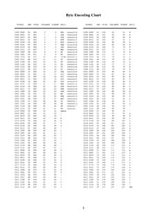
8 // Fixed resistance in the voltage dividerfloat Rt; // Computed resistance of the thermistorVo = analogRead(ThermistorPin);Rt = R*( / float(Vo) - ); (" "); (Vo); (" "); (Rt);delay(200);}Listing 1: math:1023467 1=2 1 = 1 Floating point (467) = the division as floating point numbers instead of integers preventsrounding and therefore preserves the following out-put in the Serial voltage and resistance Measurement :Vo Rt487 how the resolution of the analog to digital converter (ADC) on the Ar-duino causes discontinuous jumps in the measured value ofRt. When the valueofVochanges from 487 to 488, the value ofRtjumps from 10863 to 10820 .The jump is due to a change in the least significant bit of the value obtainedby the 10 bit ADC, not because of a discontinuous variation in the physical4 The specific values ofVoandRtwill vary from run to run, and will depend on the charac-teristics of the fixed resistor and Thermistor used, and on the Temperature of the 25, 2013 EAS 199B Thermistor Measurement5// File: Use a voltage divider to indicate electrical resistance of a Convert the resistance to -- setup() is executed once when sketch is downloaded or Arduino is resetvoid setup() { (9600); // open serial port and set data rate to 9600 (" Thermistor Temperature Measurement :"); ("\n Vo Rt T (C)").
9 }// -- loop() is repeated indefinitelyvoid loop() {int ThermistorPin = 1; // Analog input pin for Thermistor voltageint Vo; // Integer value of voltage readingfloat R = ; // Fixed resistance in the voltage dividerfloat logRt,Rt,T;float c1 = , c2 = , c3 = ;Vo = analogRead(ThermistorPin);Rt = R*( / (float)Vo - );logRt = log(Rt);T = ( / (c1 + c2*logRt + c3*logRt*logRt*logRt ) ) - ; (" "); (Vo); (" "); (Rt); (" "); (T);delay(200);}Listing 2: Conversion of the measuredRtvalues to Temperature will resultin a corresponding jump inTvalues. Appendix A contains an analysis of thetemperature resolution limit of the Arduino as a function ComputingTfromRtAs described in the Thermistor calibration exercise, the Thermistor temperaturecan be computed with the Steinhart-Hart equationT=1c1+c2ln(R) +c3(ln(R))3(5)For the Thermistor used in this demonstration,c1= 10 3,c2= 10 4,c3= 10 in Listing 2 incorporates the eval-uate of Equation (5) into the Arduino code.
10 The substantial changes the definition of the constants for theSteinhart-Hart equation in thelocalfunction,float c1 = , c2 = , c3 = ;and the evaluation ofTwith the Steinhart-Hart equationlogRt = log(Rt);T = ( / (c1 + c2*logRt + c3*logRt*logRt*logRt ) ) - ;G. 25, 2013 EAS 199B Thermistor the following output in theSerial Temperature Measurement :Vo Rt T (C)486 output shows that a change of one unit inVocauses a change of C inthe computed Temperature . Thus, we can infer that the Temperature resolutionof this Thermistor /aduino combination is C. Note that resolution is onlya measure of the smallest difference that a sensor and instrument combinationcan detect. A resolution of C doesnotimply that theaccuracyof themeasurement is C.