100 Mhz Digital Storage Oscilloscope
Found 9 free book(s)
How to Use an Oscilloscope - learn.sparkfun
learn.sparkfun.comDigital Storage Oscilloscope - 100MHz (TBS2104) TOL-14925 Retired Favorited Favorite 3 Wish List Page 2 of 26. ... a handy, mid-level, digital oscilloscope -- as the basis for our scope discussion. Other o-scopes may look different, but they should all share a similar set of control ... often in the 100's of MHz (1E6 Hz) range.

12 THINGS TO CONSIDER WHEN CHOOSING AN …
www.mouser.comA digital storage oscilloscope (DSO, which this guide concentrates on) acquires and stores waveforms. It can show high-speed repetitive and single-shot signals across ... Entry level scopes will often have a maximum bandwidth of 100 MHz. They can accurately (within 2%) show the amplitudes of sine-wave signals up to 20 MHz.
Oscilloscope Fundamentals - Case School of Engineering
engineering.case.eduOscilloscope Fundamentals 2 www.tektronix.com ... Describe the differences between analog, digital storage, digital phosphor, and digital sampling oscilloscopes ... A processor running at a 20-MHz clock rate may well have signals with rise times similar to those of an 800-MHz

Infiniium V-Series Oscilloscopes - Keysight
www.keysight.comMay 11, 2021 · Oscilloscope bandwidth allows signal rise times to be more accurately depicted. The oscilloscope noise floor directly impacts the Y-axis voltage placement of each signal data point. The V-Series combines superiority in these characteristics with extremely low sample clock jitter (< 100 fs). This ensures the lowest
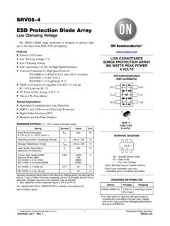
SRV05-4 ESD Protection Diode Array - ON Semiconductor
www.onsemi.com100% I @ 30 ns I @ 60 ns tP = 0.7 ns to 1 ns Figure 3. IEC61000−4−2 Spec Figure 4. Diagram of ESD Test Setup 50 Cable Device Under Test ESD Gun Oscilloscope 50 The following is taken from Application Note AND8308/D − Interpretation of Datasheet Parameters for ESD Devices. ESD Voltage Clamping For sensitive circuit elements it is important ...

2. Features and benefits PRTR5V0U2X
assets.nexperia.comTstg storage temperature -55 125 °C ESD standards compliance VESD electrostatic discharge voltage IEC 61000-4-2; contact discharge -8 8 kV 001aaa631 IPP 100 % 90 % t 30 ns 60 ns 10 % tr = 0.6 ns to 1 ns Fig. 1. ESD pulse waveform according to IEC 61000-4-2

Optocoupler, Phototransistor Output, with Base Connection
www.vishay.comCapacitance VR = 0 V, f = 1 MHz CO 25 pF Thermal resistance Rth 750 K/W 0 50 100 150 200 250 300 0 20 40 60 80 100 120 P tot - Total Power Di ss ipation (mW) T amb - Ambient Temperature (°C) Coupled device Phototransistor IR-diode
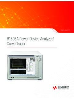
B1505A Power Device Analyzer/Curve Tracer
www.keysight.comNov 07, 2019 · B1514A Medium Current Source Monitor Unit (MCSMU) 1 -30 V to 30 V, -100 mA to 100 mA -30 V to 30 V, -1 A to 1 A (Pulse only) 200 nV, 10 pA B1520A1 Multi Frequency Capacitance Measurement Unit (MFCMU) 1 1 kHz to 5 MHz 1. N1300A-100 SMU CMU Unify Unit (SCUU) is not supported for the B1505A. 1. The total number of installed HPSMU
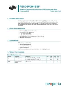
PESD5V0H1BSF - Nexperia
assets.nexperia.com100%IPP;8µs 50%IPP;20µs Fig. 1. 8/20 µs pulse waveform according to IEC 61000-4-5 and IEC 61643-321 001aaa631 IPP 100 % 90 % t 30 ns 60 ns 10 % tr= 0.6 ns to 1 ns Fig. 2. ESD pulse waveform according to IEC 61000-4-2