100 transistor circuits
Found 8 free book(s)
Go to: 1 - 100 Transistor Circuits Go to: 100 IC Circuits
www.radioman33.comIn this Transistor Circuits ebook, we have presented about 100 interesting circuits using transistors and chips. In most cases the IC will contain 10 - 100 transistors, cost less than the individual components and take up much less board-space. They also save a lot of circuit designing and quite often consume less current than discrete components.
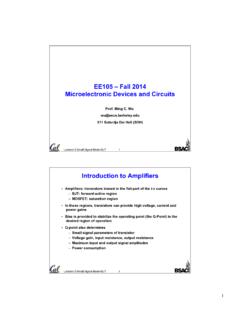
EE105 – Fall 2014 Microelectronic Devices and Circuits
inst.eecs.berkeley.educircuits and inductors by short circuits. – Find Q-point from dc equivalent circuit by using appropriate large-signal transistor model. • ac analysis: – Find ac equivalent circuit by replacing all capacitors by short circuits, inductors by open circuits, dc voltage sources by ground connections and dc current sources by open circuits.
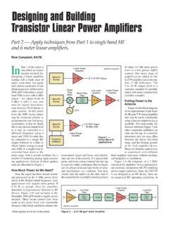
Designing and Building Transistor Linear Power Amplifiers
www.arrl.orgpower supply for an inexpensive transistor, and any efficiency I would have gained by using an expensive 13.8 V linear RF power transistor in one of Granberg’s wonderfully engineered circuits is more than offset by Figure 3 — 7 MHz linear amplifier based on …

Chapter 5 BJT Biasing Circuits
www.bu.edu.eg1. Determine the Q-point and construct dc load line for this transistor. Figure 5.26 For problem 1. [7] 2. Assume DC = 100 and I E I C. (a) Find V E, V C (b) Determine Q-point of this transistor (c) Construct DC load line and plot Q-point (d) Calculate IC if R B is changed from 10 k to be 1 k Figure 5.27 For problem 2.

ON Semiconductor Is Now
www.onsemi.comdevice. The voltage drop for the N-channel transistor is 60 mV and is 100 mV for the P-channel transistor. As a final example, consider an application with an 850 mA maximum load current. The 30 m N-channel transistor’s power loss is 21.7 mW compared to the 36.1 mW power loss of the 50 m P-channel transistor of similar die size.

ENGN 2211 Electronic Circuits and Devices Problem Set #8 ...
users.cecs.anu.edu.auENGN 2211 Electronic Circuits and Devices Problem Set #8 BJT CE Amplifier Circuits Q1 Consider the common-emitter BJT amplifier circuit shown in Figure 1. Assume VCC =15 V, β=150, VBE =0.7 V, RE =1 kΩ, RC =4.7 kΩ, R1 =47 kΩ, R2 =10 kΩ, RL =47 kΩ, Rs =100 Ω. RC +VCC R1 R2 RE C1 vs CE C2 Rs RL vin vo Figure 1: The circuit for Question 1 ...

CIRCUITS LABORATORY EXPERIMENT 6
classes.engineering.wustl.eduappears across the transistor collector-emitter terminals. The BJT is "saturated" if IC reaches its maximum value along the load line (IB > 100 μA). Therefore, the transistor can be operated as an OFF switch with IB = 0 μA and as an ON switch with IB = 100 μA. To operate the BJT as an amplifier, it is necessary to set the operating point in the
Simulating Switched-Capacitor Filters with SpectreRF
designers-guide.orgSimulating Switched-Capacitor Filters with SpectreRF A Simple Track and Hold 4 of 25 The Designer’s Guide Community www.designers-guide.org (freq2 = 10.1kHz ampl2 = 0 fundname2 = “input2”).Initially, the waveshape is set to a fixed value by type = dc.Later, the alter statement named enableTone1 changes the waveshape type to sine to enable the first tone.