A Converter
Found 8 free book(s)
Torque Converter Identification Catalog - TCS Products
www.tcsproducts.comconverter identifying data. A photo of the front and rear surfaces of the converter is provided when one is available. Additional data pages are included at the front of each manufacturers section again, to assist in the identification of the correct converter. Year Engine Dia Hub SPL Pilot Mount Pilot Center To Bolt Center Stall May specify ...

Switch Mode Power Supply (SMPS) Topologies
ww1.microchip.comSep 10, 2007 · inside the converter can be calculated as shown in Equation 2. EQUATION 2: SERIES-CONTROLLED REGULATOR POWER LOSS This type of converter is known as a series-controlled regulator. The ideal power loss in this converter depends on the value of the series resistance, RS, which is required to control the output voltage, VOUT, and the load current ...
LTC1966 - Precision Micropower ΔΣ RMS-to-DC Converter
www.analog.comThe LTC ®1966 is a true RMS-to-DC converter that utilizes an innovative patented DS computational technique. The internal delta sigma cir cuitry of the LTC1966 makes it sim-pler to use, more accurate, lower power and dramatically more flexible than conventional log antilog RMS-to-DC converters. The LTC1966 accepts single-ended or differential ...

Building a DC-DC Step-Down (Buck) Converter Circuit Using ...
www.egr.msu.eduThe circuit for the DC-DC step-down (Buck) converter would have the LM7809 voltage regulator, two capacitors with capacitance value of 0.33µF and 0.1µF. Figure 3 below shows the corresponding circuit, Figure 3: DC-DC step-down (Buck) converter circuit. Step 1: The LM7809 voltage regulator is placed in the desired position on the circuit board.

AN-1484Designing A SEPIC Converter - Texas Instruments
www.ti.comFigure 3. SEPIC Converter Switching Waveforms (VQ1: Q1 Drain to Source Voltage) 2 Duty Cycle Consideration For a SEPIC converter operating in a continuous conduction mode (CCM), the duty cycle is given by: (1) VD is the forward voltage drop of the diode D1. The maximum duty cycle is: (2) 3 Inductor Selection
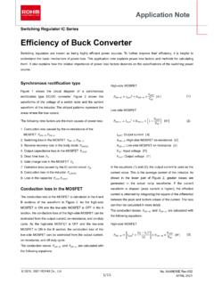
Efficiency of Buck Converter - Rohm
fscdn.rohm.comEfficiency of Buck Converter Switching regulators are known as being highly efficient power sources. To further improve their efficiency, it is helpful to understand the basic mechanism of power loss. This application note explains power loss factors and methods for calculating them.
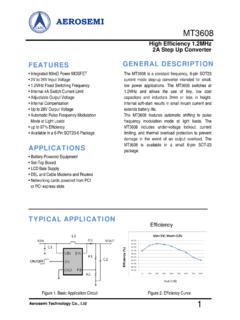
AEROSEMI - Olimex
www.olimex.comcurrent mode stepup converter i- ntended for small, low power applications. The switches at MT3608 1.2MHz and allows the use of tiny, low cost capacitors and inductors 2mm or less in height. Internal soft-start results in small inrush current and extends battery life. The MT3608 features automatic shifting to pulse
7 Series FPGAs and Zynq-7000 SoC XADC Dual 12-Bit ... - Xilinx
www.xilinx.com7 Series FPGAs and Zynq-7000 SoC XADC Dual 12-Bit 1 MSPS Analog-to-Digital Converter User Guide UG480 (v1.10.1) July 23, 2018