Adders
Found 9 free book(s)
Binary Adders: Half Adders and Full Adders
www.edwardbosworth.comBinary Adders: Half Adders and Full Adders In this set of slides, we present the two basic types of adders: 1. Half adders, and 2. Full adders. Each type of adder functions to add two binary bits. In order to understand the functioning of either of these circuits, we must speak of arithmetic in terms that I learned in the second grade.
Digital Logic Design - 國立臺灣大學
www.csie.ntu.edu.twAdders Half-adder ¾Adds two bits Produces a sumand carry ¾Problem: Cannot use it to build larger inputs FllFull-adder ¾Adds three 1-bit values Like half-adder, produces a sumand carry ¾Allows building N-bit adders Simple technique Connect Cout of one adder to Cin of the next These are called ripple-carry adders

Ripple Carry and Carry Lookahead Adders - UVic.ca
www.ece.uvic.cawill use 1-bit full adders as components. 5. Model a 16-bit adder in a separate file using the VHDL structural description. The 16-bit adder will use 4-bit ripple carry adders as components. 6. The 16-bit adder has two inputs and of type bitvectorrepresenting the addend and augend; and 1-bit input signal of type bitrepresenting the carry in ...
16 Bit Digital Adders - Concordia University
users.encs.concordia.caThe parallel prefix adder is a kind of carry look-ahead adders that accelerates a n-bit addition by means of a parallel prefix carry tree. A block diagram of a prefix adder Input bit propagate, generate, and not kill cells Output sum cells The prefix carry tree G z "group generate"x signal across the bits from x up to z
4.0 SOHC Tech - Super Six Motorsports
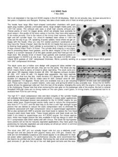
www.supersixmotorsports.comsizes are the way to go. OK, speaking of power adders, heres where we get un-happy with the heads—they are very thin walled aluminum construction, and they have the “Swiss Cheese” deck like the 94-95 3.8 heads that were so prone to blowing head gaskets. Each cylinder is surrounded by 4 head bolt holes and 8 large coolant holes!

VLSI Design - Tutorialspoint
www.tutorialspoint.comVLSI Design 5 Figure: Structural hierarchy of 16 bit adder circuit Here, the whole chip of 16 bit adder is divided into four modules of 4-bit adders. Further, dividing the 4-bit adder into 1-bit adder or half adder. 1 bit addition is the simplest

Arithmetic / Logic Unit – ALU Design
web.cse.ohio-state.edu• 32-bit adder is built out of 32 1-bit adders Input Output Figure B.5.2 Figure B.5.5 1-bit Adder 1-bit Adder Truth Table From the truth table and after minimization, we can have this design for CarryOut Figure B.5.3 . 4 g. babic Presentation F 7 32-bit Adder + + + + a0 b0 a2 b2 a1 b1 a31 b31 sum0 sum31 sum2 sum1 Cout Cin Cout Cout Cout ...
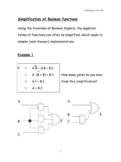
Simplification of Boolean functions
homepage.cs.uiowa.eduadders, subtractors, and all the circuits that we have studied so far Sequential circuits. The output depends not only on the current values of the inputs, but also on their past values. These hold the secret of how to memorize information. We will study sequential circuits later.
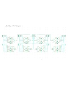
Circuit Diagram: 4-to-1 Multiplexer
www.cs.uic.educonnected full adders. I tested this circuit with all possible inputs since there are only 8 possible combi nations as shown in the previous truth table. Circuit Diagram: Closer Look at Previous Circuits Below is an example of a single-bit 4-to-1 multiplexer used in my